|
Steve, I don't mean to step on your toes here, but some things you've described don't match what' I see in the OE diagram. I do agree with much of your post, but offer the following because I think it helps the reader to distinguish a relay's Coil voltage from it's output ("relayed") voltage. I'm addressing the RSR first because in operation it gets energized first (like the older System relay in the White case, which it now replaces). I'm using a 1995 OE diagram, which shows just the single "Main" pump. [I think the '94 is the same, but that's a guess.]
The Radio (Interference) Suppression Relay (RSR)is located under the hood near the coolant resevoir. This relay is rectangular and black. The 12V power to this relay's Coil (and to it's input switched voltage) come directly from the battery and remain constant. This relay is controlled (on-off) by a (negative) Coil ground signal from ECU 21, [when the Ignition Key is turned On, putting 12v on ECU 35]. The RSR output terminal 87 (3) supplies 12V power to the fuel injectors, Mass airflow meter, Idle air control valve, ECU 9, and Fuel Pump relay Coil+ side terminal 86 (2).
[The Pump relay's ground side 85(4) will be controlled by ECU 20, when Ignition timing pulses are detected at ECU 1.]
The Pump Relay is on the relay terminal rack located behind the ash tray. This small blue cube relay powers both the intank (if present) and Main fuel pumps. The constant 12V power to this relay's Coil comes directly from fuse #1 (25 amp) . This relay is operated (on-off) by a (negative) ground signal from ECU terminal 20). The 12V switched output from this relay powers the Main fuel pump directly (thru the 25 amp fuse) and also powers the in-tank fuel pump (if present) and the oxygen sensor heater thru fuse #11 (15 amp).
--
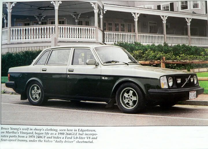
Bruce Young, '93 940-NA (current), 240s (one V8), 140s, 122s, since '63.
|