|
|
|
This has got to be a textbook problem but I've searched a ton of threads and don't see my problem described exactly anywhere.
When I turn my ignition 'on' (but not to 'start'), I've read that I should see all my idiot lights illuminated, as this is a kind of 'test' position:
My batt light is the ONLY one that lights.
When I start the car, they should all turn off.
Istead, my batt light remains on, and will stay on, until the revs are increased to maybe 1500rpms approx., at which time the light goes off, and I almost swear I can hear a surge of power when it does. Almost as if the alternator was acting like an engine brake.
Anyone ever seen these symptoms?
Especially just the light staying on at idle.....and turning off after it's revved?
Thanks
|
|
-
|
|
|
Major change of state here.
Last night I received a big tach and a good number of replacement bulbs for my dash, but not before my car stopped dead in my driveway after arriving home last night after work.
Bulletin: car was not charging whatsoever with gauge cluster removed.
I figured last weekend, that it would benefit my dash, gauge cluster and all the 30 year old wiring and connectors, if I stopped removing it and installing it every time I tried yet a different stage of troubleshooting of my problem, so I left it out all week, after having read they are 'safe' to drive with the cluster removed.
Well, whatever the heck happened, I ran the battery down to nothing.
I did sense slow cranking the last couple of days.
So here is the new development:
After installing the tach (unrelated) and replacing ALL of the idiot lights last night, the time had finally come to move to the next stage of troubleshooting my initial problem of: charge light staying illuminated and alternator not exciting itself, would only go out after it met a certain RPM.
So I move the key to lamp-test position: WOW! all lamps lit up!
I fire it up...starts great, idles smooth...so sign of BATT light at all.
Checked charging, a healthy 13.7V.
So it looks like...possibly...the fact that so many bulbs were removed, might have had something to do with my BATT light staying on.
I don't know how, I don't know why, but it seems to now excite the alternator properly.
Now I only have one remaining problem: the 'bad bulb' sensor comes on any time any of the operational lights are on. If markers, headlights, or brake lights are engaged, the 'bad bulb' light comes on, even though all those bulbs are working good.
|
|
-

|
|
Good to hear back from you. I suppose you're OK with the mystery remaining, so, drive on. Now the battery light goes out when you start the car, and the idiot lights do light with the ignition on.
New thread for the BFWS trouble.
--
Art Benstein near Baltimore
"Tho' I've belted you and flayed you,
By the livin' Gawd that made you,
You're a better man than I am, Gunga Din!”
|
|
-
|
|
|
The replies to this post have been great.
I have something to compare that might help.
Its an amazon but same idea. It exhibits the same symptom. Of course it only has the amp light. 2 different alternators (because I upgraded for more amps)
do it.
It has a custom dash with a non stock amp light. I think amp light is a different resistance causing the current flow to the exciter to be different. You may have that different resistance because you have less lamps illuminated. As I remember there are Diodes in series with the other lamps and not the amp light. If these diodes are blown for some reason it might exhibit your symptoms. I don't have a diagram in front of me so maybe Art can chime in on this.
|
|
-
|
|
|
If you want to investigate your Amazon's manifestation of this residual magnetism effect, assuming we are talking about Bosch internal regulator alternators, try removing the D+ wire from the alt with the problem, with the car stalled. Connect a voltmeter to the alt's D+ terminal. Start the car and observe the voltage at the D+ terminal as you open the throttle on the V8*.
*Assuming your handle is double entendre... Edit: Sorry, I see we've already been onto this topic... https://www.brickboard.com/RWD/volvo/1620537/220/240/260/280/dash_warning_lights_flicker_coming_highway.html
Regardless of how you've isolated the dual alternators' outputs to the starting battery the D+ terminal should rise as the rotor's residual magnetism begins to induce current in the stator. But you can't count on residual magnetism; not all have enough to start the alternator charging. However, in the case it does, the regulator and brushes need to at least be present for any appreciable charging current to be developed once the rpm has self-excited the Bosch alternator.
Troubleshooting by correspondence depends heavily on specific details, as well as general concepts being understood the same way by both parties. When we discuss a particular year 240, for instance, it is important to know it hasn't been modified, so that the details aren't missed. Talking about warning light behavior when someone has removed them changes the game considerably. The diodes which isolate the switches for brake failure, parking brake, and bulb failure are there for lamp test only, and there's no reasonable way for them to be damaged.
--
Art Benstein near Baltimore
There was a priests' retreat at some retreat house and during the course of it the retreat master asked them to break up into groups of three. They were then to share their deepest darkest secrets, things they had never shared with anyone else ever.
The Dominican priest after much hemming and hawing said that he was an alcoholic. He had been so ashamed to tell anyone before. He drank all the time and just couldn't kick the problem. He was so glad that in the sacredness of this small group he could share this and now he felt so good, so free.
The Franciscan priest hesitated, but finally said he thought he could trust the other two and that his problem was gambling. He had been unable to control his urge to go to bet way beyond his means. He was also very ashamed of his habit and was so grateful that he could finally share it in such a context with his fellow priest.
It was the Jesuit's turn. He told the other two that he was grateful for their openness and honesty. He said he was so ashamed of his own problem. He had been working on it for years but hadn't yet gotten a handle on it. He had tried hypnosis and therapy, but nothing, he said, had helped him overcome his compulsion to gossip.
|
|
-
|
|
|
The Amazon is a B20 the V8 is a 245.
Being a bit lazy I just blip the throttle on the Amazon and off goes the lamp and I happily drive away. Can't help but smile when I drive it.
|
|
-
|
|
|
That the Amazon is not V8 powered is one of the most important and relevant details I lacked. Mysteries overcome by a smile are the best!
--
Art Benstein near Baltimore
Everything is okay in the end. If it's not okay, it isn't the end.
|
|
-
|
|
|
Holy cow, so I ran some tests last night and I have a much different problem than I thought I had.
I made the mistake of assuming that 12V was getting to the exciter post on the alternator because the light was coming on during lamp test then staying on after starting.
I had thought that it was finding ground through the alternator etc.
So, tried the exciter post with key in 'on' position, BATT light lit, NO VOLTAGE PRESENT.
12.44V at batt.
Started car, no voltage present at exciter, and 12V at batt.
Gave it some revs, light goes out, (audible load removed from motor, once the light goes out, you can audibly hear the motor and blower motor etc. increase) 13.44V at battery now.
So, the old factory connector looked darkened and suspect, and the wire was quite stiff. I decided to cut the end off and crimp another ring on there. Still no voltage.
(did not have the alternator pictures Art supplied so couldn't really see the ground coming off the alternator but I'm going to have to check that later)
I did test batt +, to the alternator housing with the meter and it appeared that the housing is at least grounded.
Could be a broken wire under the crank/front etc. but I have to say, this car is an 89 and is in good shape. I haven't found much of any kind of mods anywhere on the car and everything is in stock condition.
Pulled the dash cluster and realized that only 4 of the idiot lights even have bulbs in there. I will need to order more bulbs online, I can't find them around here, not even at the euro parts place.
So, I need to get this exciter wire working, and it's probably unrelated to the whole 'lamp-test' issue.
Art supplied me with the signal path to check out the exciter and I'll get on that. But in the meantime...I am wondering how/why I misunderstood why the BATT light was on at all. How is it even turning on at all if it's not grounding the alternator? I guess there is the possibility it's ground out on the block or on some metal somewhere....although that seems unlikely to me.
How else could that BATT bulb be finding ground?
|
|
-
|
|
|
"How else could that BATT bulb be finding ground?"
The batt bulb will come on regardless of which direction the current flows through it. And it doesn't take a full 12V to light it. You can see it with as little as 1.0V across the filament, although it is comparatively dim.
The problem I see is you don't have any other bulbs to compare its brightness. That someone removed them should tell you something I don't need to repeat.
Do you need a wiring diagram? http://volvowiringdiagrams.com
My suggestion? Make sure the ground for the alternator is sound, and that the alternator will charge at idle. To verify, remove the D+ connector from the alt, start the car, verify no charging (12V), then while idling momentarily bridge D+ and B+ with a test light or jumper. If it begins and remains charging (13.6V) the brushes and regulator are functioning. This will at least get you out of the engine compartment, perhaps, and back into the warm cabin.
--
Art Benstein near Baltimore
There is always a right way and a wrong way to proceed: Two Jesuit novices both wanted a cigarette while they prayed. They decided to ask their superior for permission. The first asked, but was told no. A little while later he spotted his friend smoking. "Why did the superior allow you to smoke, but not me?" he asked. His friend replied, "Because you asked if you could smoke while you prayed, and I asked if I could pray while I smoked!"
|
|
-
|
|
|
Quickly bridged the D+ B+ this morning with a screwdriver a few moments after first start.
Audible surge instantly in rpm and BATT light went out immediately.
I think this is pointing to an exciter circuit problem.
I'm taking this afternoon off to putter on the Volvo, will be putting her up on ramps to confirm good ground from alternator housing and inspect lower sections of alt. harness.
|
|
-
|
|
|
Ha ha, yeah the sabotage theory, sure, that could absolutely be some part of things. But I just wanted to reiterate, this car only had a couple of owners, was treated quite well, is basically unmolested.
Runs and drives fantastic! (and zero electrical gremlins that I have found so far, besides lamp-test)
I've fallen in love with it, for recent the couple weeks I've driven it so far.(bought in late august and been slowly validating all systems and doing overdue maintenance items)
If they had problems with idiot lights staying on, then yeah, someone may have removed (more than 1?) I'm just not overly suspicious about this. But maybe I'd better get that oil gauge connected and double checked asap though. (I want to go to a manual oil gauge and am desperately seeking a gauge trio cluster)
In fact, this car was not even for sale, I was literally hunting for Volvos and found it in a back yard of a house for sale. I approached the owners, it was their daughters who had owned it for many years and her dad had been doing maintenance on it and gave up when the trailing arm bushings got really bad. It had been driven regularly then parked for a couple of years.
I will verify the good ground (now that I know it's almost out of sight and quite difficult to get at, I didn't know exactly what I was looking at this morning in the snowstorm)
I'm certain that it's charging once it excites itself as I've seen those readings across the battery, however, I am going to do the bridging step as you've described Art, to fully validate the alternator/regulator/exciter inner workings are good. Thanks again.
|
|
-
|
|
|
I think Art is right about the exciter wire. Volvo ran this wire across the front bottom of the engine just above the oil pan where it is subjected to heat oil etc. I had all kinds of similar electrical gremlins due to this. Mine was pretty much destroyed. I replaced the wire and put good sleeve insulation on the new one. Problem solved
|
|
-
|
|
|
Hey Beast, what do you mean that Art is right about the exciter?
I think Art was starting me down a comprehensive troubleshooting path to find out why my lamp-test stage wasn't working but the exciter just got involved in that process.
My exciter wire seems to be exhibiting a good 12V source from ignition side, and it's also finding ground somewhere good too, it's the fact that it absolutely, reliably goes out when the engine reaches a certain rev point (when the alternator self-excites) and seems to start charging.
Those two tests I outlined should put most the exciter wire questions to rest.
I'm kinda thinking my reg/brush module is really worn, and that my lamp-test issue might be unrelated.
Luckily, it looks like a Bosch original, so I hope that means I can just replace that little module. The bearings seemed to be okay when I had the belts off a few weeks ago doing the timing belt and water pump.
|
|
-
|
|
|
Change out the Voltage Regulator in the back of the Alternator. Brushes will have to wear in on the replacement Voltage Regulator since the armature will not be flat.
|
|
-
|
|
|
This is a common issue, brushes could be replaced but it's easier to get a new module.
Dan
|
|
-
posted by
someone claiming to be cdcrawford
on
Tue Nov 7 21:45 CST 2017 [ RELATED]
|
|
Because the light goes off above 1500 rpm, I am going to suggest (perhaps incorrectly) that your voltage regulator is "bad" OR your brushes are worn down. The good news, if this diagnosis happens to be correct, is that the voltage regulator and brush pack can be replaced as a unit for around $60.00 without replacing the entire alternator.
I have a great deal of respect for Art Benstein and the content of his posts, but I am having a little trouble with the idea of your problem being one of wiring given that the light extinguishes at >1500 rpm. I've had this symptom before on my 240s and it was the regulator/brushes every time. If I am correct (it happens now and then!), that light will eventually, with a few more miles on the car, stay illuminated constantly as the alternator will soon stop charging.
|
|
-
|
|
|
Sometimes I get wrapped up in trying to explain one cause for multiple symptoms. Worn brushes or a defective regulator could easily explain the charging behavior, and the lack of lamp test for the oil, CEL, OD, and service could be an entirely separate issue.
We should always start with the basics. Make sure the ground for the alternator is sound, and that the alternator will charge at idle. To verify, remove the D+ connector from the alt, start the car, verify no charging (12V), then while idling momentarily bridge D+ and B+ with a test light or jumper. If it begins and remains charging (13.6V) the brushes and regulator are functioning.

--
Art Benstein near Baltimore
The friars were behind in their belfry payments, so they opened up a small florist shop to raise funds. Since everyone liked to buy flowers from the men of God, a rival florist across town thought the competition was unfair. He asked the good fathers to close down, but they would not. He went back and begged the friars to close. They ignored him. So, the rival florist hired Hugh MacTaggart, the roughest and most vicious thug in town to persuade them to close. Hugh beat up the friars and trashed their store, saying he'd be back if they didn't close up shop. Terrified, they did so, thereby proving that Hugh, and only Hugh, can prevent florist friars.
|
|
-
|
|
|
I am so thankful for this site, what a great community.
In my gut, I have been suspecting worn brushes/reg, but as Art said, the lamp-test thing is kinda bizarre in it's own way.
I'm going to check the ground and run the test exactly as Art described, with the BATT light 'on', when running.
THEN, I'm going to rev it until it goes out (to self-excite the alternator), and try it again.
If it's what we are suspecting, there should be no charging during the first test, and it should be charging during the second.
I don't care how cold it is, this is happening after work!
|
|
-
|
|
|
Yes this is kind of a 'textbook' problem. More often found on a car with mechanical speedometer and a leaky windshield.
But I looked over some of your earlier posts, deciding you probably are not dealing with an 85 or earlier 240. Maybe yours is the 89 you had the oil mess with. In that case, a good guess would be the result of some monkeying with the instrument panel resulting in an open circuit at the flex fuse. How about other symptoms? Gauges work? Good temp and fuel readings? Are you saying even the oil light does not pass lamp test?
--
Art Benstein near Baltimore
Did you hear about the Buddhist who refused Novocaine during the root canal? He wanted to transcend dental medication.
|
|
-
|
|
|
A 'flex fuse' is something new I've never heard of.
You are correct, it's an '89 in above average, stock condition for the most part.
Thankfully I've only come across one electrical mod, and it was quite inexplicable. It was a wire jumped from the fog light lead (which has tested dead) jumped over to possibly the dimmer lead on the Volvo radio.
Then another jumper from the radio down into the heater area, which I've cut and terminated because I couldn't get to where it was going.
No frigging idea what this guy had those two leads connected to, and honestly can't remember if my BATT light has always displayed this condition, but I am thinking it has.
I also remember having multiple VW's that exhibited this exact behaviour, and I was always told it was 'normal' back then.
Fast forward to now, and I'd read somewhere that it was the same kinda thing, the alternator wouldn't charge until you reached a few revs. Later, in reading more articles, I realize I have a problem.
It may be just that the alternator is on it's way out, haven't had it tested or done any multimeter tests on my own yet. But what worries me more
is that I'm not seeing ANY lamp tests besides the BATT light.
This is slightly worrisome.
I have had the cluster in and out a number of times and am familiar with it.
I have not tested every bulb in the cluster, nor am I sure if it's still got every bulb (and bulb holder) needed as there seems to be a lot of vacant holes!
A good diagram of what SHOULD be there would be helpful.
The fuel and temp gauges seem to be working nicely, and I was going to do the temp gauge bypass thing where you bypass the dummy board so you can get a more accurate reading all the time.
Can you suggest anything else to check?
In my mind...grounding out the small wire should light up all my lamps, is that correct?
I don't think it's going to be successful because currently the BATT light shines nice and bright steady and that means it's finding a ground.
How do all the other lamps get energized at this lamp-test phase?
I must also add however, that my ignition switch seems slightly worn, not in a loose way, but some keys are very tight for it to turn, and if not careful, may not return readily on it's own from 'start' position. Being aware of it means you always manually kinda move it off 'start' back to 'run' without thinking about it.
However one more piece...it is possible in 'run' to move it just a hair backwards, and the headlight circuit will be cut.
I thought I had a major problem one night with my headlights (I've only had this car on the road for a few weeks) but I realized a jiggle of the ignition brought them back on.
However I HAVE kinda jiggled the ignition in the 'run' position..and I'm still not getting the lamp-test.
Suggested next steps, if any? (and what's a flex fuse?)
|
|
-
|
|
|
Try to remember the year pulldown when starting a new thread.
OK, having working gauges and no lamp test at all makes this not a 'textbook' case of missing exciter path. The routine trouble, which might include a damaged flex fuse, takes out the gauge power too.
The flex fuse is a piece of flexible circuit on mylar used to bridge two screw terminals behind the speedometer gauge. It is usually disturbed when someone goes to pull the gauge to fix the odometer and doesn't realize the screws need not be removed.
The biggest challenges come to a new owner who finds the previous owner modified things without documenting, and the worst of them, those done to get the car sold. Typical motivations would be a check engine light, or oil pressure warning. That you have NO working lamps at lamp test yet do have working gauges eliminates the natural causes I know of, and has me suspecting the man-made troubles.
All you can do is trace the voltage. Start by fixing the alternator exciter. The alternator is probably OK because it self-excites when the residual magnetism in the rotor is enough to induce field at hi revs. This is normal. Yes, disconnecting and grounding that small red D+ wire (key on engine stalled) at the alternator should give lamp test to BAT, BRAKE FAIL, PARKING, and BULB OUT idiot lamps. The power for those lamps comes through the speedometer gauge, flex fuse, and cluster circuit traces from the ignition switch. But that power is the same needed to power the temp and fuel gauges. So you need to find out why they work, but the lamp test (warning lamps) does not.
What I would do in your shoes is pull the cluster (you've done that several times?) and go over the traces looking for signs of the previous owner, or other damage that pops out visually. Then if I saw nothing, I'd use my test lamp or multimeter to trace the voltage (cramped work on top of the steering column) to find the break. Unless someone has modified something, it has to be in the instrument panel, I think.
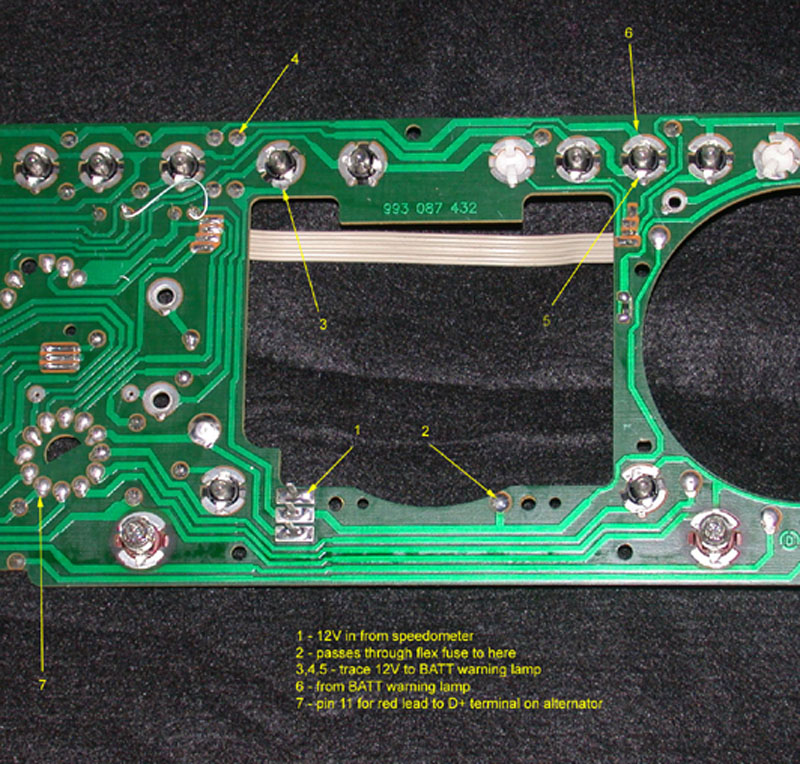
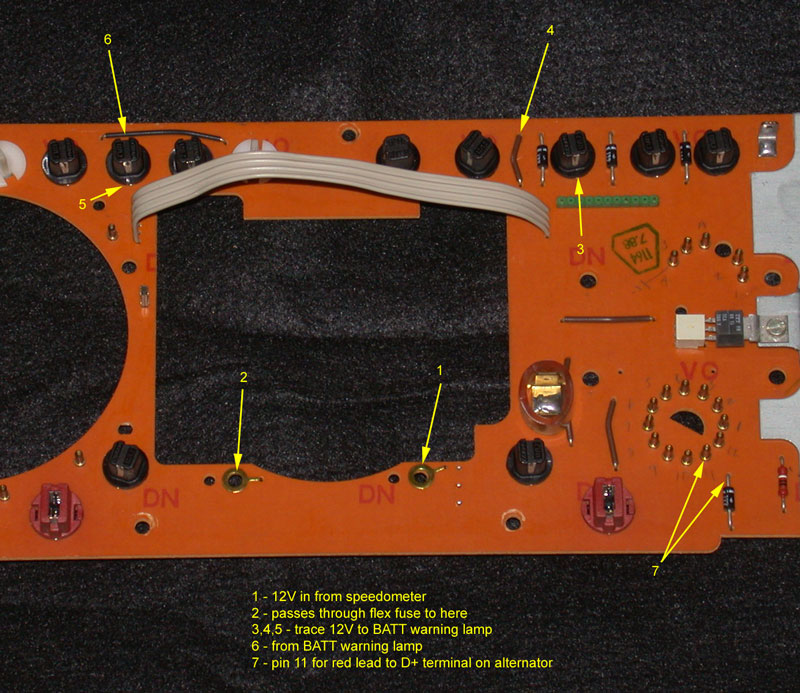
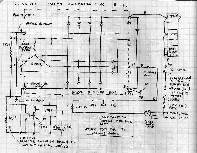
Here's the path of that voltage from ignition switch to the small red wire on the alt:
--
Art Benstein near Baltimore
A group of chess enthusiasts checked into a hotel and were standing in the lobby discussing their recent tournament victories. After about an hour, the manager came out of his office and asked them to disperse. "But why?" they asked, as they moved away. "Because," he said, "I can't stand chess nuts boasting in an open foyer."
|
|
-
|
|
|
Thanks Art, for your detailed reply.
You say 'start by fixing the alternator exciter' first.
So...you're thinking the exciter is not working?
How could it be illuminated if it were not finding it's ground through the alternator?
Best test for it would be to remove it from alternator, turn key to 'on' position and test voltage with a meter or test light, correct?
Not sure why you think the exciter is not working?
(I'm probably not understanding something here)
|
|
-
|
|
|
Right.
Terminology is the problem. I should have said get your alternator exciter working first, which still might sound like I want you to do something physically to the alternator, but what I intend is for you to get the excitation voltage to it from the cluster, before diverting your attention to the warning lamp problems.
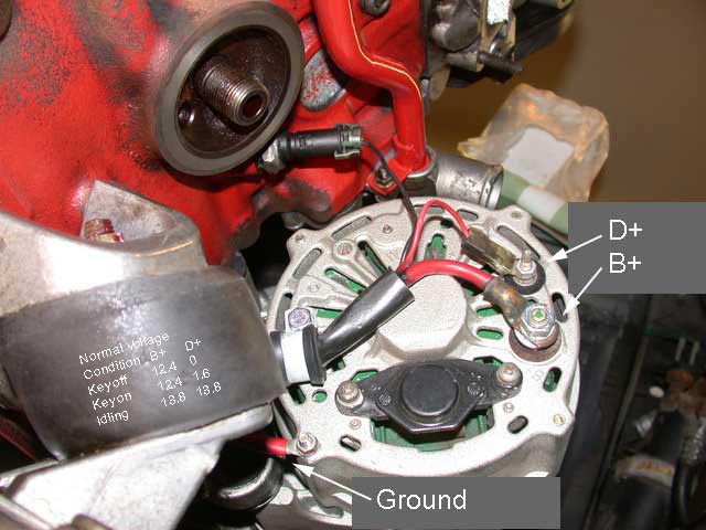
The cluster's job in this regard is to provide battery voltage to pin 11 on the round connector, which eventually ties to the D+ terminal on the alternator. Pull the small red lead from the alternator, connect it to a small test light that is well grounded (don't trust the alternator housing) and look for battery with key on. Fix this first.
Here's a functional view of the path from battery to D+:
--
Art Benstein near Baltimore
A woman has twins and gives them up for adoption. One of them goes to a family in Egypt and is named Ahmal. The other goes to a family in Spain; they name him Juan. Years later, Juan sends a picture of himself to his birth mother. Upon receiving the picture, she tells her husband that she wishes she also had a picture of Ahmal. Her husband responds, "They're twins! If you've seen Juan, you've seen Ahmal."
|
|
-
|
|
|
Excellent, thanks Art!
I'll update the post with what I find!
|
|
-
|
|
|
Yeah so...
...I energized the exciter post with the batt post and 'voila', instant surge in RPM and BATT light instantly goes out in dash.
Exciter wire seemingly dead. Wire was stiff, old connector looked suspect": Re-terminated ring, dead.
Inspected the harness, factory ground link appears in excellent and original condition. No real damage could be seen leading up under around crank snout.
But then, as it disappears under the intake, who knows...
...looking for a hint on where to hit next, bulkhead connector (which I've not yet delved into, because everything 'was fine') or go back to the instrument cluster?
Art: you had supplied a hand-drawn diagram of the entire circuit and a link to the wiring diagrams. I've spent a good amount of time reading schematic diagrams but some are easier than others. Should I just start with your trace test of the instrument circuit board?
Thanks in Canada
|
|
-
-
|
|
|
of COURSE I have a test light and meter Art!
I only flail and sound like I don't.
|
|
-
|
|
|
OK, lets start with the test light. Describe it for me. Humor me and make no assumptions.
You could kill two birds by also including a little detail about your meter too.
--
Art Benstein near Baltimore
Real Engineers consider themselves well dressed if their socks match.
|
|
-
|
|
|
Ha ha, sure man, I am a 20-year veteran audio visual tech and musician who has done all kinds of soldering and minor electrical repair, backyard mechanic, motorcyclist who has resurrected or have owned maybe 10 vintage machines or so over the years. I know what capacitors and resistors and diodes do, I'm the guy that usually fixes the electrical on friend's cars/RV's, I'm the guy who throws in a car stereo for a case of beer etc.
I've got a basic understanding of voltage, current, amperage, continuity and electrical components, but I've never done any formal training and it's all just job-by-job and what I pick up along the way.
I've got pretty good hands as far as working with vintage and 'unobtainable' parts, (gentle, gentle) relatively good common sense (disconnecting battery) and can visualize things in my small brain relatively well. I can follow along pretty good.
But I've never really cared or had the interest to deep-dive into complex electronics or sophisticated automotive electrical. I've got a relatively cheap ($30) digital multi-meter and I literally wore out my Snap-On test light over 20 years and am now using what you guys down south would call a 'harbor freight special'. It's never failed but I always test it before I use it.
|
|
-
|
|
|
Great to know your hands have "been on." Last summer I heard a rumor we might be getting a Harbor Freight right in town to save me that two hour excursion.
The reason I ask about the test light is I want to know how much current it uses. Any light will indicate presence of voltage if unlimited current is available; if I use an LED for a test light, I can see voltage through very high resistances, like corrosion or even a wet finger. If I use an automotive lamp like a brake light for a test light, I can know at least several amps are available; that the 12V supply is not impaired by a poor connection. But for the alternator exciter circuit, we need to know something in the range of 100mA is available, so a test lamp with that rating is equivalent to the dash warning lights used in that circuit.
When you verified the alternator needed stimulation to charge, it sounded to me like you did not disconnect the D+ wire from the alternator as I expected you to, but bridged D+ and B+ with it in place, because you said the dash light immediately went out. Couldn't happen any other way.
But there exists the possibility of a defect in the regulator not tested by that direct bridging without removing the D+ circuit from the panel. In fact, I get the idea the faston is no longer there, and you've terminated the red wire in a ring lug directly to the alternator's D+ stud.
Additionally, unable to explain why bulbs were missing, you leave me to wonder what the bulb thief was trying to do: Perhaps she was trying to convert the warning lamps to LED as it is the cool thing to do, right? I can't be there to check, so I fall back on basic methodology.
Assuming your Snap-On test light is roughly 1 watt, lets try this, following each step exactly, or at least you will say something if not:
1) Disconnect the small red lead from the alternator D+ lug.
2) Connect your test lamp between the end of the loose red lead and ground at the radio suppression bond strap between the firewall and cam cover.
3) Turn the ignition key to KP-II
4) Observe the test lamp, and either compare its brightness to 12V (at the B+ lug) and/or measure the voltage with your meter with the lamp connected.
5) Remove the test lamp from the red wire and the ground strap, and turn the key off.
6) Connect the test lamp between the B+ and D+ terminals on the alternator. Observe the lamp and report its brightness and/or measure the voltage with your meter with the lamp connected. Connect the meter between the ground strap and D+ side of the lamp.
7) Remove the meter and ensure the test lamp wire is clear of rotating parts and start the motor.
8) Observe and report the test lamp and measure the charging voltage at the battery.
9) Shut off the motor and post a reply here with your observations and I will attempt to explain them.
--
Art Benstein near Baltimore
Real Engineers buy their spouses a set of matched screwdrivers for their birthday.
|
|
-
|
|
|
Okay, here we go:
'The reason I ask about the test light is I want to know how much current it uses. Any light will indicate presence of voltage if unlimited current is available; if I use an LED for a test light, I can see voltage through very high resistances, like corrosion or even a wet finger. If I use an automotive lamp like a brake light for a test light, I can know at least several amps are available; that the 12V supply is not impaired by a poor connection. But for the alternator exciter circuit, we need to know something in the range of 100mA is available, so a test lamp with that rating is equivalent to the dash warning lights used in that circuit.'
- CONFIRMED - test light I'm using uses a common automotive bulb, incandescent model #1893
'When you verified the alternator needed stimulation to charge, it sounded to me like you did not disconnect the D+ wire from the alternator as I expected you to, but bridged D+ and B+ with it in place, because you said the dash light immediately went out. Couldn't happen any other way.'
- I believe this is what I did, yes, and did it again, just to make sure, but this time, I did something different. I setup up a jumper between B+ and D+ and got in the car to see what state the BATT light would be in when I hit KP-II on the ignition, (KP-II is the lamp test position, right?) Anyhow, when I got in the car, lo and behold, the BATT light was lit up with no key in the ignition. In my simple primate mind, this proves that the integrity of the D+ wire, (small red one, freshly terminated with a new d-ring) leads back up to the dash successfully and is reaching the BATT bulb for sure. I hope this is true, would seem to eliminate problems along the entire route of the wire, leaving the problems probably to the circuit board, the alternator/regulator, or maybe, just maybe......the ignition switch. When I hit KP-II, I believe the light went out, and car started and BATT light never lit...indicating I guess, that the alternator was excited, as anticipated by bridging directly. Anyhow, thought I'd just mention that.
'But there exists the possibility of a defect in the regulator not tested by that direct bridging without removing the D+ circuit from the panel. In fact, I get the idea the faston is no longer there, and you've terminated the red wire in a ring lug directly to the alternator's D+ stud.'
- Your first part, (I think) is the basis of the testing you outline below. Your second sentence, just confirms that you understand that I removed the factory d-ring and plastic insulator (was not a faston, or a removable style) trimmed the wire and re-terminated it, because the original fitting was very dark and 1/2 inch long and wire could have been corroded or broken in there, and I wanted to be sure.
'Additionally, unable to explain why bulbs were missing, you leave me to wonder what the bulb thief was trying to do: Perhaps she was trying to convert the warning lamps to LED as it is the cool thing to do, right? I can't be there to check, so I fall back on basic methodology.'
- There were no teens trying to modify this car, anywhere, but it may have been a dodgy mechanic that removed them on an unsuspecting owner after being unable to figure out why some were lighting up? grasping there. but I wouldn't rule out that some may have been removed because of some real (but maybe minor) electrical or sensor problem. There is also this: these bulbs are very, very hard to find in Canada and I am having to order replacements from the states, I live in a major centre and none of the parts outlets can even order them and the euro and VW specialist part place can't even get them. They aren't even listed? It's weird. Anyway, there is the remote possibility that they could have burned out and were removed and never replaced. Who knows, but I can't wait to fill it with new bulbs.
Assuming your Snap-On test light is roughly 1 watt, lets try this, following each step exactly, or at least you will say something if not:
'1) Disconnect the small red lead from the alternator D+ lug.
2) Connect your test lamp between the end of the loose red lead and ground at the radio suppression bond strap between the firewall and cam cover.
3) Turn the ignition key to KP-II'
4) Observe the test lamp, and either compare its brightness to 12V (at the B+ lug) and/or measure the voltage with your meter with the lamp connected. '
-Tried just the test lamp first: does not light. Then tried with the meter inline, and sure enough, with the meter in series after the test light, we had 12.11V. (standing voltage across batt was 12.37 first thing, with no test equipment connected).
'5) Remove the test lamp from the red wire and the ground strap, and turn the key off.
6) Connect the test lamp between the B+ and D+ terminals on the alternator. Observe the lamp and report its brightness and/or measure the voltage with your meter with the lamp connected. Connect the meter between the ground strap and D+ side of the lamp.'
-This seemed a bit weird, because to complete the circuit going from B+ through test light, through meter, then to D+, THEN bridging from there to ground strap, seemed to provide a direct ground and didn't really include the D+ post's internals or circuit much. Anyway, I tested both ways, once directly as requested, and once just in a circuit from B+ through light, through meter, directly to D+ post. To strap was 12.39, without going to strap, just to D+ was 12.37.
'7) Remove the meter and ensure the test lamp wire is clear of rotating parts and start the motor.
8) Observe and report the test lamp and measure the charging voltage at the battery.
9) Shut off the motor and post a reply here with your observations and I will attempt to explain them.'
-Connected everything, and test light lit up. Started car, light went out, read 13.64V. Shut car off, light lit up again.
-Only one other observation here, when introducing my meter into the test circuit, every time I did, the lamp would no longer light, although I always placed the meter AFTER the lamp, with the correct polarity, (and it would always reflect those 12V figures fine) Not sure why the lamp can't find ground through the meter well enough to light. Maybe there is some weird thing in the meter that's stopping it from being able to do that. If you want I can do some tests that lamp/meter test circuit directly with the battery '+ and -' etc. to rule anything out.
|
|
-
|
|
|
Closer, but no cigar won.
Your test lamp is a 5W lamp, so I don't expect it will glow much with the current needed to check the regulator. In the hope I would know just how much current was being drawn, I asked you to check with a voltmeter, but somehow I didn't explain how a voltmeter is used.
With the test light (and you should really find a smaller one for this instance) connected between D+ and B+ you should see the same brilliance as you would see in the dashboard for lamp test. With a 5-watt lamp you might not see much.
To convey that across the miles you could describe the voltage at the D+ terminal by simultaneously bridging (not inserting) your meter between ground and the D+ terminal. Inserting the meter into a circuit is a way of measuring current, and you're not practically going to do that with your multimeter in the voltage mode.
Sorry about the lack of parts up there. I used to travel to Canada sometimes in the 90's doing troubleshooting on some mainframe computers when it was a serious offense to be potentially taking work from a Canadian, meaning any tools/equipment I would bring from the US might not make it through customs. So I've collected a few unique hand tools purchased in Canada. Good tools too.
Anyway, I agree the wire is there, yes, but just because it is there doesn't mean it doesn't have a "problem." With the readings you gave me, that wire could indeed have a tiny nick in its insulation, behind which all of the copper has become a somewhat conductive glob of verdigris. It happens.
The same symptom could result if someone replaced the BATT lamp with an LED substitute. It happens. These are just guesses though, and they might jump you to a conclusion, but the sure way to success is diagnosis.
The purpose of this exercise was to divide the system between the alternator assembly and the cluster/wiring. With the exception of that rare and unexpected case when a regulator may need too much stimulation current, I think you've proved the alternator is OK with your 5W test lamp, and the red wire delivers a "voltage" from the cluster but with insufficient current.
Try this next: Find a piece of wire 8 feet long, strip one end and tie it through the D+ ring lug (disconnected from the alt of course) making a reliable test connection. Then use your ohmmeter in the lowest scale to read resistance between the other end of that wire and the red wire at pin 11 of the round connector on the back of the cluster (also disconnected from the cluster). TLDR; check continuity of the exciter wire. If you see a high resistance, like over an ohm if your meter will discern that, wiggle that 8-place gray connector on the firewall for a first suspect. While you have the cluster out, make sure the BATT lamp is an incandescent lamp. Those warning lamps rarely go bad because they are rarely used.
And when measuring voltage, the rule is to add the meter to the circuit in parallel, not insert it in series.
--
Art Benstein near Baltimore
Real Engineers say "It's 70 degrees Fahrenheit, 25 degrees Celsius, and 298 Kelvin" and all you say is "Isn't it a nice day?"
|
|
-
|
|
|
Man, we are getting really far out of synch here.
1.I couldn't conclude exactly what we were trying to measure during the last round of tests, or I would have tested parallel, but I was approaching each task by a completely different mindset, trying to insert the meter into the circuit the way I did. Essentially all of those tests were useless, should we just step back and redo them?
2.The measurements you were looking for: I think the term 'voltmeter made me think you were looking for voltages instead of mA readings. I am still not exactly sure what you were after?
3.I can simply take a known-good 1.2W dash bulb and make a test tool with it. This seems like it would be the quickest and easiest method forward, no?
4.'To convey that across the miles you could describe the voltage at the D+ terminal by simultaneously bridging (not inserting) your meter between ground and the D+ terminal. Inserting the meter into a circuit is a way of measuring current, and you're not practically going to do that with your multimeter in the voltage mode.'
- I think what you are saying here (without saying it) , is to put my multimeter into amperage mode, not voltage mode, right? I think the most important part of every test from now on is stating if you are looking for a voltage answer or a mA answer. That would seem to help. Bridging and inserting is becoming very confusing here. I've looked at a number of diagrams now and completely understand the difference between measuring current flow via series-style test, and measuring voltage by placing the probes on either side of whatever it is you are trying to measure in a parallel style test. All of this was terribly unclear during the first round of tests.
5. 'Anyway, I agree the wire is there, yes, but just because it is there doesn't mean it doesn't have a "problem." With the readings you gave me, that wire could indeed have a tiny nick in its insulation, behind which all of the copper has become a somewhat conductive glob of verdigris. It happens.'
-Agreed. The wire could still be totally screwed up.
6. I'll do the resistance test as soon as I get home after work today. Sounds super easy. Now as far as checking the bulb...I have checked every bulb in the cluster for continuity and found a couple of duds and a few good ones left. In fact, this weekend, I ended up replacing all of the burnt out mini-bulbs in the heater console as well...I could only find two, and they were both burned out.
Let me know if you want me to re-run any of the tests, if indeed you were looking for mA readings, instead of DCV readings.
|
|
-
|
|
|
1) No. I was asking you to measure voltage, not current. Always use your voltmeter in parallel and your ammeter in series. I'm not asking anyone to use an ammeter here. Too many pitfalls for the weekend warrior.
2) No. I would interpret the current based on knowing what your test light was made from and the voltage reading I was having you make.
3) Yes, you could, if you just wanted to be absolutely certain the alt is good, as claiming to be cdcrawford suggested. But I'm fairly, mostly, betting-sure you proved it is OK and the exciter wire is just not delivering enough current to start the charging.
4) No. Not a chance. If you had done what I asked, exactly*, you would have measured the voltage at the D+ terminal with respect to ground while being supplied current through the test light. That information would tell me approximately how much current was being passed by the test lamp, given I know what that test lamp uses at 12V, and what the regulator sinks. If you want to repeat the test with a 1-watt lamp, it is up to you. The object is to vindicate the alternator/regulator so you can move on to troubleshoot the car/cluster.
5) Good. Maybe here we are in sync. So why not check the wire end-to-end? That's the simple backyard mechanic method. I would look for voltage drop, but I don't expect that to be something I could talk you through in an afternoon.
6) I used to collect bulbs at the junkyard. They were always free. Those used for lighting, for example, like the bulbs you pulled from the heater controls were often at the end of life or dead. The warning lamps were always, and I mean in every case I found, like new even after 20 years. Guess I never found a car driven around with its warning lights on. Stop by, I'll give you a handful.
* 6) Connect the test lamp between the B+ and D+ terminals on the alternator. Observe the lamp and report its brightness and/or measure the voltage with your meter with the lamp connected. Connect the meter between the ground strap and D+ side of the lamp.
--
Art Benstein near Baltimore
Real Engineers' politics run towards acquiring a parking space with their name on it and an office with a window.
|
|
-
|
|
|
I can't find the exact thread where I replied last but here goes:
Art: last thing you had asked me was to do the 8' jumper directly from the red wire (off the post) up, around and into the cabin, to measure ohms to #11 in the main cluster harness.
I finally got some time to do that and the results are like, 0.1, or .001 or .002 type range.
I tried to make sure I was in the right mode etc., I tested through my own body which settled somewhere near 11 when the probe was an inch away from the wire on my finger. I'm now using a professional meter as well, a Fluke 115.
So, everything I could do, resistance looks very, low. Very low.
I'm keeping the cluster out for the next few days though because I am waiting on a tach and a full compliment of bulbs coming from a Volvo speciality wrecker located on Vancouver Island I just learned about this week.
So that should be good.
Anyhow, not sure what to do at this point.
If I understand right, do you think the red wire is just not delivering enough amperage to excite?
Could that regulator module be like....worn so it needs way more juice than usual to pass through or something? like some kinda diode in there?
Because when we 'proved' that piece was working by jumping it to B+, man, that's straight to battery and would be full blast.
|
|
-
|
|
|
Great, sounds like you've gained some confidence in the red wire's integrity, so now the instrument cluster is your focus.
--
Art Benstein near Baltimore
A famous Viking explorer returned home from a voyage and found his name missing from the town register. His wife insisted on complaining to the local civic official who apologized profusely saying, "I must have taken Leif off my census."
|
|
-
|
|
|
The plot thickens:
I've got the cluster out right now waiting on the tach and bulbs from the Volvo specialty wrecker.
While I had it in the house and holding it up to the light to look at the idiot lamp holes, I noticed the remnants of adhesive tape, on the clear cluster lens.....right over top of where the 'check engine' light is!
Starting to realize why some bulbs may have been removed.
Not the end of the world though as the car is still running great.
I really don't know where to go from here except to install some manual oil and temp gauges so I don't blow it up.
|
|
|
|
|


