|
|
|
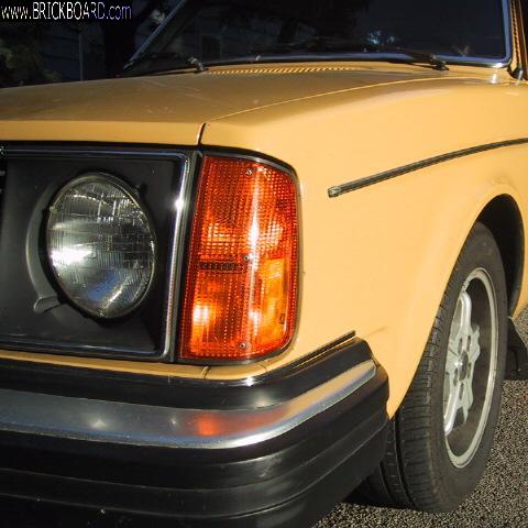
I'm attempting to repair a goofy bulb sensor -the later red-orange one made by Hella for Volvo. These were used in all the later RWDs. I've isolated it to voltage from the brake light switch badly leaking out into the dash indicator reed switch circuit. Barely getting 1/2 volt at all three brake lamps (obviously none will light). I've successfully re-soldered this bulb relay before (based on notes I write on the case), but this time no such luck. Single diode tests okay, single 47 uF cap tests okay, four resistors likely okay, that pretty much leaves either a physical short somewhere or a leaky transistor (T1, T2, or T3, all are NPN audio amplifier transistors worth an entire 1 cent each in large quantities). On close inspection and cleaning, there are no solder bridges or corrosion seen at or between any solder joints or traces, plus I re-flowed all I could easily get at. I'm not about to waste more time and pull the transistors for testing unless I figure someone else has succeded doing this.
Art, it's clear from your old turbobricks posts that you know (or once knew, laugh) a hell of a lot about these troublesome little beasts. Any thoughts? Anyone else?
I've also read in old posts that a simple bypass bulb sensor with the base board jumpered to bypass all the circuitry makes for brighter bulbs. Opposite to modern cars with LED bulbs, our old Volvos are well known for their weak lighting. I'm having a bit of difficulty believing that bypassing the bulb sensor will make much difference as I'm not seeing much resistance in the circuits. Anyone care to comment on that thought?
Anyone care to comment about the aftermarket Kaehler bulb sensors compared to the original Volvo ones made by Hella? IMO, the Kaehler fuel pump relays are far superior to the original Volvo white ones made by Stribel so I figure Kaehler has an above average reputation for quality. Hoping that holds true for the bulb sensor as I can get them considerably cheaper.
--
Dave -still with 940's, prev 740/240/140/120 You'd think I'd have learned by now
|
|
|
|
|
I should almost start a new thread on this, but it's a follow-on to my original problem and Art will be following this so I'm hoping for his thoughts.
I replaced the failed bulb sensor relay with a KAE (Kaehler, Germany) as they're about half the price of the genuine Volvo/Hella ones plus not many suppliers bother carrying the grossly expensive Volve ones anymore, including FCPEuro.
Since then, I've had nothing but aggravation with the KAE relay, two of them in fact (second one an exchange unit for the first). Both intermittently misbehaved in the same way, turning the warning light on for 1-3 mins for no good reason then going out. I swapped both of them into two different cars -similar misbehaviour. Swapped in a known good Volvo relay -no problem in either car. I've done the usual bulb/socket cleaning/greasing in both cars and swapping bulbs left right. Both cars have stock lighting and I try to match brands left/right whenever possible, especially the headlamps.
Anyone else had problems with these KAE bulb sensors? The are very few reviews, but none indicate such problems.
I thought KAE stuff was pretty good, although my local Volvo indie guru feels otherwise and won't touch them anymore. I always used to go with the KAE 240 fuel pump relays, in fact I much preferred them over the Volvo/Striebel (higher amp rating can better handle the increased draw of worn pumps).
I'm at the stage of thinking the KAE design is simply too sensitive for my lighting and charging circuits. It may also just be a bad batch as the second relay came from the same supplier just a week later. KAE in Germany doesn't seem to offer customer support, leastwise not on their English pages, nor does my supplier and they're not keen to replace the unit a second time.
It's inconsistent which lighting circuit irritates them. In one car, it only seems irritated when the headlamps are on -momentarily turning off the headlights resets the indicator for at least 15 mins. In the other car, it's much more irritable and I've yet to identify a pattern -momentarily switching off the headlights, park lights or touching the brakes usually resets it for a few minutes. The second KAE was initially less sensitive than the first, but the sensitivity seems to be increasing with age, initially one false indication every few trips, now multiple times every trip.
Any thoughts Art, others? An errant capacitor, resistor or semiconductor perhaps?
I've yet to open it up. Before I throw it in the back of a box and put in my bridged sensor, I may give it a re-solder just for the heck of it to make myself feel useful.
--
Dave -still with 940's, prev 740/240/140/120 You'd think I'd have learned by now
|
|

|
|
Hi Dave,
"I should almost start a new thread on this ..."
I agree. It is another "what vendor of replacement parts for 30-year old cars makes good stuff" question, which depends entirely on opinions and current experience, neither of which I can offer help on. I'm thinking maybe I'm the only one besides yourself following this old thread.
"An errant capacitor, resistor or semiconductor perhaps?"
Resistors, semiconductor devices, and even electrolytic capacitors (despite the rep they got from those rushed to the motherboard market 20 years ago) are much more reliable than simple connections. But if it is a brand-related issue, such as a workaround to a Hella patent perhaps, it could be related to components other than connections. My first guess would be the bifilar-wound current sense coils and their magnetic reed switches. Those are the pieces that make for differential current sensitivity.
"I may give it a re-solder just for the heck of it to make myself feel useful."
Yes, have a look at the soldering. That's a variable that comes under the "connections" heading. In any case, pull it apart and see what you can see that makes it different from a Hella unit. I've never seen one made by Kaehler. And today, with lead missing, solder is even more brittle.
"I always used to go with the KAE 240 fuel pump relays, in fact I much preferred them over the Volvo/Striebel (higher amp rating can better handle the increased draw of worn pumps)."
This is, in my opinion a myth. The "amp rating" is about relay contacts, and no Volvo or Stribel relay in my experience ever came close to being insufficiently rated for relay contacts in comparison to even locked-rotor current for the main fuel pump. The failures have been with the circuit board soldering, and the moisture-exposed relay socket faston connectors and crimps. The protecting fuse is rated for less current than the relays. However "amp rating" sure sells to mechanics.
Once you get the problem to be consistent, what you can try is what I should have done first, instead of jumping to the sedan tail lights and their perennial corrosion issues: Bridge the outputs to left and right at the relay pins. For the tail lights, bridge 58L and 58R. For the brake lamps, 54L and 54R. I simply short the pins together with a screwdriver tip, but for the headlights the pins are not adjacent; 56bL and 56bR. Every time I've had a warning for the headlights, a headlamp was dark.
It takes a little coordination, screwdriver and relay in left hand, and right hand to start the car, turn the light switch, poke at the brake pedal, etc., but you will force the currents to be equal and thereby prove which direction you need to investigate.
Caveat -- the nature of European street parking separates the input side of the circuit for the parking lamps, so before convicting the BFWS, make sure that corrosion on the separate fuses (240 at least) is not the trouble with the parking light bulb warning.
--
Art Benstein near Baltimore
It's always darkest before dawn. So if you're going to steal your neighbor's newspaper, that's the time to do it.
|
|
|
|
As far as I can tell, Art last posted to the BB on March 17. This absence is unusual.
I hope everything is okay with him.
--
'80 DL 2 door, '89 DL Wagon, '15 XC70 T6
|
|
|
|
|
Yes, now that you mention it, I did notice a lack of Art postings recently. I also hope he's okay. Hope he's off on a cruise rather than stuck in bed with a nasty winter flu or some such. There's a nasty flu going around in this corner of the world in the past couple months that can lay people up for a week or two. Not sure if the current flu vaccine works for it. So far we've managed to escape it.
--
Dave -still with 940's, prev 740/240/140/120 You'd think I'd have learned by now
|
|

|
|
Indeed, Art Benstein's most recent post is 17 MARCH 2019.
Profile:
https://www.brickboard.com/RWD/user_data.htm?uid=27
Art last posted on Turbobricks in this thread on 04-04-2019, 08:41 AM
http://forums.turbobricks.com/showthread.php?t=348426
Art posts his email at the bottom of the main cleanflametrap page.
http://cleanflametrap.com/
Hope that helps you.
--
Donate NOW! Give your brickboard.com a big DONATION!!! Find the  on brickboard pages! on brickboard pages!
|
|
|
|
|
Ok, here's a post for the "ALL/ALL" forum.
Really I'm here, but "anyone else" is doing fine as most of us are just looking for expedient solutions and bypasses to irritations, not the sort of root cause analysis to waste Jarrod's bandwidth. I'll post maybe if a question hasn't been covered a dozen times before with my photos and links.
Dave, if none of your brake lights are lighting because of the bulb-out sensor, the problem is both simple and common. The solder joint between terminal 54 and the sense coils is broken. This is the connection with the highest current.
--
Art Benstein near Baltimore
"Well, here we are, Mr. Pilgrim, trapped in the amber of this moment. There is no why." -KV
|
|
|
|
|
art-you will be missed. i've been to your posting page just to read what you've said from time to time-still do. not sure i will be missed as i've given up on silver bullets required by those that post. even if i have 1 to give, it's not heeded until all else failed. tried to play, but.....
your message reminds me of how things are in the business in general. can't diagnose it, no time. obd says it's the o2 sensor, just change it. and so it goes, chuck.
|
|
|
|
|
Thanks, Art. If you can remember that old childhood taunt, it sure worked for me as your suggestion made me go back and have another look at my bulb sensor even though I'd gone over it a number of times with a fine toothed comb (kept getting caught up in the coils).
You surmised a broken circuit between terminal 54 (from the brake switch) and the sense coils (which then go to the brake lights). That was my first thought also, but it had checked out okay. My tracing had it narrowed down to 54 majorly leaking out (as in shorting) into the dash bulb light circuit (31-K), hence power from the brake light switch taking the easy path to ground rather than illuminating the brake lights. Why it wasn't blowing a fuse was a bit beyond me at the time, but it seems it was going through enough circuitry and wiring to put a small load on it.
Here now, thanks to your encouragement, is the conclusion of my tale.
Double checking everything in case you were right, I also re-checked the short I'd previously seen into 31-K, but it was no longer there. What?? With alligator clips on assorted pins, all of a sudden the meter beeped while I was handling the bulb sensor. Twisting the boards a little was all it took to make the short happen and go away. OMG, like maybe a bad solder bridge I'd missed that was barely shorting under the wrong tension, like when being inserted in the relay tray socket. Well, 30 minutes later with my trusty meter, dental pick, plastic tweezers and the brightest light and best magnification I could muster, I finally isolated it as an intermittent bridge between the reed switch and the inside of the brake light inductance coil. Trying to tweak and centre (yes, that's how we spell it up here) the wire leads for the reed switch only provided limited benefit, so I decided to remove it, straighten it and put an insulating sleeve on the leads to guarantee it would stay away from the inside of the coil. I almost had it all back together when the ceramic sleeve holding the teensy reed switch inside decided to crumble -end of that thought, so heck, why not just leave the reed switch out permanently, next best thing to a bypass. Then, during subsequent handling and testing, another reed switch shorted out, obviously the ceramic on these reed switches is now crispy fragile after all these years. So, high time to declare this bulb sensor relay toast and re-wire it as a bridge. As a bit of a purist, I'll probably put in a new bulb sensor at some point as they are mildly useful especially as I'm not the principal driver, but for now I'll use the bypass.
BTW, Can you remember these were introduced in the 1974 140s and first known as a Bulb Integrity Sensor, whereas they are now known variously as Bulb Failure Warning Sensor (later 240 manuals), Bulb Failure Sensor (740 manual), Bulb Malfunction Indicator (940 manual), and in catalogues as Bulb Failure Relay or just Bulb Sensor (most aftermarket catalogues) and even Brake Light Relay (in one catalogue) -makes them a little trickier to find when google searching for prices.
--
Dave -still with 940's, prev 740/240/140/120 You'd think I'd have learned by now
|
|
|
|
|
Dave,
The trouble with your brake lights was not a short. It was an open.
--
Art Benstein near Baltimore
Asked to explain the term "American values", Vidal replied, "Lying and cheating. There's nothing better."
|
|
|
|
|
Dave Barton (www.davebarton.com) sells the little pins needed to completely bypass the troublesome sensor and has diagrams on his site telling you exactly how to plug your newly made bypass wires/jumpers into your factory plug after you're removed the sensor. Then throw the sensor as far as you can. Check for bad bulbs by looking every now and again.
--
82 242-6.2L; '17 Mazda3; '16 Crosstrek
|
|
|
|
|
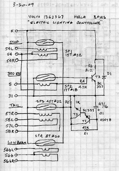
Yes, Dave's got great stuff and tons of good info on his site at davebarton.com. It would actually be quite easy to make up your own from an old one. Just cut through the middle of all the long pins and posts above the base board, bend them around as needed to make access easier and solder in jumper wires to complete all circuits except for the dash bulb (p31-pK). With a bit of visual and meter tracing you can figure out the circuits. For actual pin assignements there's a good diagram in the green electrical manuals (assorted green manuals can be found on line with google, any later year that uses that sensor will do). Plus on turbobricks there's a couple of old posts by Art (as cleanframetrap) with a good hand drawn schematic.
Thinking about my problem overnight, it occurred to me there's one more, and very likely possibility and that's a wire going through one of the inductance coils shorting to the inside of the coil. Difficult to look through some of the coils so I'll have to do some more tracing today. Kinda fiddly to unsolder some of the connections to isolate circuits for testing so I'm hoping my ESR meter can find the short in circuit. If you're not familair with them, ESR meters can test caps in circuit, but I'm not overly familiar with some of the other tricks they can do. I picked up a build-it-yoursef kit for an ESR meter from an electronics distributor for like $29 some 16 years ago as a fun project -kinds neat, but I don't do enough electronics to use it often plus it's not much good for surface caps which are increasingly used on PCBs these days.
I'm still curious whether bypassing the sensor will make a noticeable difference in bulb brightness as one person claimed many years back. If I give up on the reapir and build a jumpered one I'll post back on this thread.
--
Dave -still with 940's, prev 740/240/140/120 You'd think I'd have learned by now
|
|
|
|
|
As a promised follow-up here, I made up a jumpered bulb sensor and wanted to know if it really made much difference in bulb brightness. The answer, as I rather suspected, is no appreciable difference.
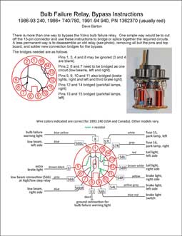
For those wanting to do a bypass for the bulb sensor relay, there are three options:
1) Remove the bulb from the instrument cluster. If it's just a nuisance bulb out indicator then that' great. But some of those old sensors can develop more troubleshome shorts and breaks that cause real problems, not just a false or intermittent indicator.
2) Quick and dirty is to use a small selection of two-legged and three-legged male jumper wires and insert them directly into the relay tray socket to re-connect the original circuits that branched out in the bulb sensor (see Dave Barton's web site for more info).
3) A more elegant solution, leastwise in my mind, is to crack open the sensor, cut-off and de-solder all conections above the base board, and solder in jumper wires on the base board to replace all the circuitry you just removed (except of course for the dash bulb). It's best if you have a proper wiring diagram -there are three types of bulb sensors that were used. Refer to green manuals, Dave Barton's webs site and/or sketches that can be found on Turbobricks. On the later sensors, for example, you can do most of the needed jumpering by soldering short U-jumpers wires between adjacent pin holes on the board, plus two longer jumper wires that have to cross the board a short way (insulated wires are best there). Trickiest bit is not letting your solder unintentionally bridge between adjacent pins -inspect your handiwork carefully.
--
Dave -still with 940's, prev 740/240/140/120 You'd think I'd have learned by now
|
|
|
|
|
Hi Dave,
I changed the topic heading from repair to delete, just in case there is some lonesome soul out there who arrives here wishing to repair a bulb failure warning sensor rather than bypass it. I knew this thread was heading for the delete category as soon as I read your original posts, with references to reed switches, Dave Barton, transistors, diodes, capacitors, and by gosh, an ESR meter. None of those things have any involvement whatsoever in lighting your dark brake lamps!
The theory of the sensor is to take the smallest samples possible of the current to the individual lamps to provide an alert when a path fails. That tiny sample is just enough to magnetically move the iron reed in the glass tube, yet because of the exponent in the relation between voltage and power, that reduction in lamp brightness is tiny-squared. What goes on with the stuff that turns on the warning indicator I've explained somewhat in that link Kitty posted Deleting Bulb Failure Circuits (TB)
You won't notice the difference between a bypassed unit and having the sentry in place, doing its job for lighting integrity, safety, and avoiding increasingly dangerous traffic stops -- unless you could perform the bypass at night while your headlamps are illuminating a reflective sign down a dark highway, switching it in and out observing the increase in light output.
The trouble with these 86 and later sensors might be said to have its root cause in the high-mounted brake light mandate. Hella was building them with reliable point-to-point wiring previously, then with the added complexity stuffed into the same form factor put the new circuitry on three tiers. The interconnection had to pass the high lamp current through wave-soldered pins whose joints eventually fractured like most every other high current solder connection in the 80's-era "electronic" relays.
That broken solder connection in the path from pin 54 is what kept your brake lights from lighting. It was difficult to build, and hard to get in there to repair. It is even hard to photograph. What's easy is to ruin one trying.
It would only be luck that you could diagnose this open circuit with the continuity beeper on a multimeter. Like you noticed, a fractured solder joint is mechanically sensitive. Diagnosis is done in circuit, under load, not by "testing" components; you have battery voltage on pin 54 and none on pin 54R, 54L, or 54S. I understand this is pretty easy poking a test light or meter probe in the back of the socket in a 240, but maybe a challenge doing it in the ashtray of a 7/9.
While I like to have mine working, and by "mine" I mean those in the cars my family drives, I do have one unit which was ruined converted to a "test" relay.
Delete the Bulb Sensor:


--
Art Benstein near Baltimore
"Sometimes I think the greatest talent of all is perseverance. But only sometimes." -Mitch Albom
|
|
|
|
|
Excellent photos and diagrams so that others can see what we've been talking about.
Thanks Art, for your detailed analysis and explanations of my bulb sensor problems. Yes, some of my early speculation on what was going on was rather implausible when I go back to read it, although things were perhaps more complicated than you imagined. The jumpering you did to make your Test sensor is more or less exactly what I accomplished the other day, except your soldering skills are perhaps a little tidier than mine (I wasn't planning for a photo shoot).
To belabor this thread more than I should, and what with the brickboard messaging facility perpetually broken (and me being too lazy to find your email address), what follows is not for people's future technical reference, just for you as a backwards look at my diagnosis and speculation in relation to what you've said and a distillation of the pertinent diagnostic steps I took. Being thrown a few curves along the way, I was very much grasping at straws when I turned to you and the brickboard. There are also some details that I didn't properly clarify as I wasn't expecting you to be doing such a thorough job of remote diagnosis (like I should expect anything less).
Like you, I totally suspected a cold or cracked solder joint on the brake light circuit (54->54R/54L/S). All my initial symptoms said so. It was the first circuit I carefully inspected and resoldered. The whole time my meter said I had continuity, so I did indeed turn to a load test. Out of the relay tray, with 12 volts directly from the brake light switch to 54 (also proving the integrity of the brake switch), the brake circuit in the sensor functioned exactly as expected, a nice 12 volts out on all the brake light pins. When installed in the relay tray and with a few test wires looped around the pins, things were very different, only residual millivolts out to the brake lights. Just to be sure, I tested the wiring from the relay tray back through the brake lights, but that all checked out.
[BTW, 740/940 relay trays aren't that horrid to work with, better than playing hide and seek and needing to remove the glove box and trying to reach for some of them wedged in a rats nest of wires under a 240 dash. The smaller front row relays have at least some access when the tray is unclipped and pulled forward a bit. Removing the above storage tray allows you minimal access to everything and with a bit more effort you can pull it right out and flip it over if the wire harness is completely free and properly folded at the back.]
One thing I did not clarify that may have caused you to hold your open brake light circuit thought while I was off on assorted wild tangents was that when my DVM saw continuity change (beeped) during handling while grabbing and twisting the stack in my hands, it was not while being clipped to 54 and 54R/54L/S, it was between 54 and K-31 (K-31 being the bulb sensor circuit with all the components on it like the transistors and diode that should not at all be in contact with any of the bulb circuits). My apologies, I was not specific enough and should have clarified that for you when I saw your diagnosis hold firm.
On the bench, I tried to replicate the short so I could find the highly suspected solder bridge (with all the lumens I could muster, magnifying glasses and dental pick in hand). As I tried to indicate, what I surprisingly eventually found was that just gently bending the reed switch wire going through the brake light coil was all it took to make/break the short between 54 and K-31 (K goes to ground so that was presumably how current from the brake switch was bleeding off to ground and not going through the brake bulbs). During previous repairs a year ago (to the headlight circuit), attempting to give it a bit of a refurbish, I would have re-soldered and re-centred all the reed switches to make everything good as new. I may well have accidentally cracked the reed switch ceramic coating and later on accidentally bent that wire closer to the inside of the brake light coils and it's taken over a year to wear through the thin coating on the coil wires enough to allow a short under load that only got worse during current testing and handling. When the reed switch was removed that was the end of the short and all other misbehaviour. Not content to just leave it at that and put it back in the car to live without the brake lights being sensed, I decided to slip an insulator on the other reed switches so that nothing like this would ever happen again. They likewise decided to fall apart, so at that point I declared it toast and decided to give it a lobotomy and jumper the base board for temporary use and future testing purposes.
Hopefully I've now been able explain this to your satisfaction. As always, it's been both fun and educational having such discussions with you again!
I'll leave it to some other post to get the brake light fuse amperage from you (I did blow it once during testing) as I'm sure your manuals are closer to your fingertips than mine and it's also raining out. (please just grit your teeth and try to smile at this attempt at a joke)
--
Dave -still with 940's, prev 740/240/140/120 You'd think I'd have learned by now
|
|
|
|
|
No need to apologize, Dave. The bottom line is there was no consequence to the reed switch "short" you thought you saw. The problem was simply the intermittent open circuit caused by the fractured solder on the path between pin 54 and the three sense coils leading to the brake lights. Nothing more complicated.
Using a DMM continuity buzzer can be misleading to those of us who get the DMM out maybe once or twice a year. If you were to experiment some with a variable resistance, you might get to know your particular meter and where it decides to beep or not to beep, and just how repeatable it is.
There's no such thing as "bleeding off" the brake light current to K, 31 or any other terminal. If it were a short which would affect whether your brake lamps lighted, your fuse would be instantly vaporized, and if not, the wiring would be. Sorry. You're correct, if the PM facility worked here, I could have avoided my difficult bedside manner, firmly denying your conclusions in public. Somehow I knew it would lead to that, having read your posts, so that's why I kept my words short and to the point, thinking you'd eventually get some help to see they were true.
As for my books on 7/9, I'm afraid I leave that to you folks who use the FAQ list of editor's choice posts as a reference. In a 240, the brake lights are fused at 8A.
--
Art Benstein near Baltimore
"People that can use a test light, meter, a scope, and talk to the consumer without being mean to them can do very well in this growing industry. I've been an electronics tech for 30 years so I know just how much fun this electronic stuff is." -Dave dl242gt
|
|
|
|
|
Hi Dave,
May be me? I performed the bypass on a failed red can bulb out sensor on the green 1992 Volvo 240 GL.
Dave Barton provides this info here:
https://www.240turbo.com/volvo240mods.html#bulbfailsens2
Click the image with "<<< Red Sensor 1362370: Diagram at left is for the RED 1986-93 ...."
Art posted page that includes a diagram of the black bulb out sensor. Or maybe this Turbobricks thread?:
https://forums.tbforums.com/showthread.php?t=240085
I used Art's info here yet adapted to the change for the red bulb out sensor. Than I found Dave Barton's info.
I guess you could find the info in the search or using Bing or Google searching the brickboard. I looked for an eloquent discussion as to what rear wheel is the primary drive wheel on an open differential rear axle on 240.
The headlights remain brighter. Yet as I do, I inspected and tested the entire exterior lighting system from the inner-fender B+ power distribution junction block to all bulb sockets and connections to ground. I also had to clean and reseal the lousy US-DOT plastic lens headlamp assemblies. The same for the awful flex PC board six-panel wrap around taillights in cleaning the assemblies (simple green and rather warm water) with better condition flexi PC board and correct some prior owner damage from incorrect bulb holder / bulb install. The Portland and Spokane junkyards help. To this day the exterior lighting is bright and clear. Though the halogen 9004 bulbs, a crappy system at that, age and dim. So, got a new set the best or second best Sylvania offers. Phillips or GE may make better 9004 bulbs.
Though best would be may be LED bulbs with more lumen put for the 1986+ three rear brake lights and brighter LED turn signals / front running lights.
Speaking of bandwidth, the two or three large facebook forums call the bulb out sensor a "bulb failure relay" or some such. One more way to bring them here so more donations and advert revenue for Jarrod's brickboard.com.
Each individual message is nearly nothing in bandwidth. The cost is in hosting the site, the client hosting side services, and the https TLS 1.2 in / out encryption service the brickboard uses.
The Art is correct that we want to use the search feature to find post by topic that are useful. Maybe update to the current inter-subjective (shared) notions so we can share in the best understanding or approach to the issue.
I'm more concerned about the capacitors in the engine control ECUs, Speedo / ODO, and such, as they age and fail. I'd hoped to have a D-Jetronic 140 or 164 with a few extra D-Jet ECUs as they do continue to run, yet caps, transistors, diodes, resistors do fail. A little more complicated than a Pioneer Silverface receiver amp restore! Be nice to have a basement or garage bench someday soon to do the work with soldering pencil in hand.
Also, fun to deliver useful info to the facebook Volvo RWD crowd. Many their run on the mythos that 240 and other RWD Volvo accepts abuse and neglect unendingly, and then a post about no-start, non-op, #11 fuse blows repeatedly, can't pass emissions or safety inspection, and so forth. So I try to bring them here. Yet do mention to search and than ask. Account and posting are free. As you feel free to donate!
Happy Monday!
Earl Grey Tea so Brisk and Strong ...
--
Donate NOW! Give your brickboard.com a big DONATION!!! Find the  on brickboard pages! on brickboard pages!
|
|
|
|
|


