|
|
|
1993 240 Wagon
Rear window switches are not getting power to post 4 through the yellow wire. There is no continuity from the yellow wires to the lockout switch on the driver's door. The rear windows operate just fine using the switches on the driver's door.
According to the wiring diagram, the left rear switch should have a yellow wire into the switch, and one out, but I only see one coming in.
Where is the yellow wire splice that delivers power to the rear window switches?
Thanks.
|
|
-
|
|
|
Repair successfully completed today.
I spliced in a new wire using butt connectors just behind the lockout switch and just above the fuse panel. Toughest part was pulling in through the plastic protective tubing.
Thank you for all the help. Now I'm just waiting for the weather to warm up a bit so I can repair the rear window defroster.
Thanks again!
|
|
-
|
|
|
"repair the rear window defroster."
you are fortunate, in that you have a tail-gate.
My advice for sedans: Drain all fluids, put the car up on a rotating stand. Invert the vehicle after scraping off the rear window. Make sure the Rear Windshield is level to the ground. Replace wire and metalic surround. wait 24 hrs for glue to set.
Alt: Remove the rear windshield...proceed.
Wagon: remove tail-gate. No longer a need to Invert the Body.
Proceed. as above.
Various products on the Net for 'repairing' that metalic heater compounf.
Do Your Own Research for the 'Best'.
This is not a joke.
But then I ask you---with a wagon---how big a deal is Not having that heater in the rear windshield worth---to you. On a Sedan, in the Snow Belt---rear View of the road can be a hazard. With a tail-gate---not exactly as slanted shelf that collects snow.
|
|
-

|
|
Thanks for the feedback and good to know you fixed it!
Good luck with the repair of the rear window defroster. It's the one item that never worked on either of my 245s. Broken resistive traces on the glass and broken wiring in the hinges (again!) are the common culprits.
On my previous 245, of the whole window only about a cm defrosted, so technically it was functional. On my current 245 a PO unplugged the switch and put a piece of insulating tape over the end of the connector telling me there's probably a short in the wiring somewhere (probably in the hinge area...).
Compared to some other cars I owned, a 245 has less tendency to fog up, so there's not that much incentive to fix it (knowing the traces on the window are probably broken anyway).
|
|
-
|
|
|
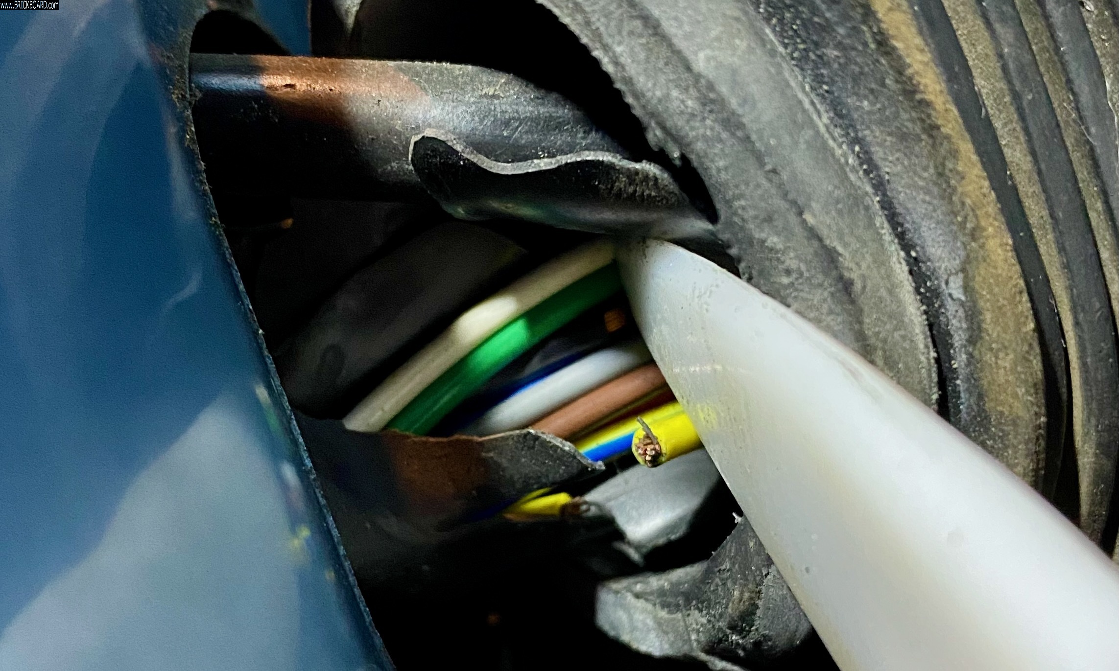
You guys were right. The yellow wire is broken in the door hinge area, inside the rubber baffle. Without too much effort, I could see at least one other wire is beginning to fail.
My initial thought is to replace the wire between the two connector blocks, without actually disturbing the connector blocks. It requires some new wire, butt connectors and heat shrink tubing.
Thoughts?
What size and type of wire should I use in this area?
Thanks again!
|
|
-
|
|
|
Replacing more or less the whole length of wire between the connectors is of course the proper approach, but of course the quality of the wire you use should be above average with a high number of strands and flexible insulation to put up with the constant movement at the door hinges so it doesn't break again anytime soon, i.e. maybe best to avoid using cheap discount primary wire.
As I mentioned, my approach is to mend the break in place and push the splice through the hinge into the pillar so that there is a fresh section of wire being flexed. There may well not be enough slack wire inside the door to accomplish this so you may need to splice in a short length at a convenient access point inside the door area.
That black wire in the background of the pic looks like just the insulation may be split. If the wire strands are all okay then consider just using electrical tape and pushing the mended point into the pillar, as in my previous throught.
That split rubber boot looks a little sad. Someone may have a better idea, but my thought would be to wrap the whole sleeve in a flexible spiral of black electrical tape. The ends will of course soon want to come loose. What I would actually do is have the split edges more or less aligned and put a thin coat of RTV along the split area with a glob around at the far ends of the sleeve. Then wrap the electrical tape as a bandage before the RTV sets so that the tape is more or less glued by RTV at the ends. Another thought would be using stretchy black rubber plumbing tape, but it may not have enough flex for the job. Thoughts from others?
--
Dave -still with 940's, prev 740/240/140/120 You'd think I'd have learned by now
|
|
-
|
|
|
Now that I see the picture you posted properly on a larger screen rather than a phone, obviously the accordion rubber sleeve is okay, it's just the harness jacket that's split where you opened it. Forget what I said about the RTV, just wrap it with electrical tape as a bandage to provide uniform support along the length through the hinge so it doesn't kink when the door opens and closes. If you wish and want to do extra to prevent the tape from unwrapping at the ends then you can always knot the electrical tape under itself at the ends.
--
Dave -still with 940's, prev 740/240/140/120 You'd think I'd have learned by now
|
|
-
|
|
|
So I've tried a few times to make the repair by pulling back the rubber boot, but I cannot seem to get enough room to do it correctly. The door does not swing open enough, and I cannot find a good way to compress the boot to get enough room.
Any tips or tricks?
I know I can remove the door panel and fuse panel, but I'm wondering if there's something I'm missing.
Thanks!
|
|
-
|
|
|
Thanks guys. I think I'm going to pull the door panel and fuse block to do it right. I have a good roll of flexible cable I used to reground the rear door hatch, and this should work well here. The only problem is that it's one color.
When I was last operating on the fuse panel, I noticed a think insulation layer over the body work that covers a wide area, including access to the wires coming through the hinge area. It's attached the to body work quite well. I remember trying to look behind it, but could not detach it without damaging it.
Anyone know the material, or can recommend any solutions they've tried? I want to be prepared.
Thanks!
|
|
-
|
|
|
If I couldn't get in with a crimp tool, I would try to fit a crimp tube, solder the connection and slide the tube over it and crimp it with hot air.
I know Dave warned against soldering because it would introduce a stiff bit but I don't see the problem.
Yes, the solder connection is stiff, but it's not going to suffer from flexing. The wire on both sides of the solder connection will. But the same thing will happen to the wire if you fit the crimp boot. The next time it breaks will be right behind either connection.
Either way you do it seems like a temporary fix to me at best. How long? Your guess is as good as mine.
(IMHO) this WAS the trick. The tip is to put in the extra effort to remove panels to get better access and to replace a longer length of wire and assess the state the other wires are in and replace any that look or feel dodgy.
|
|
-
|
|
|
I'm trying to remember if I've ever needed to pull the fuse panel to get to the other end of the wire so I could pull it back and do the splice behind the fuse panel. I vaguely recall having enough wire exposed at the hinge to be able to strip the end and attach a sleeve butt crimp connector then pushing that splice further in toward the pillar to get it out of the flexing area. I also vaguely recall not having enough slack wire inside the door and adding in a short length at a convenient location.
If you're having problems then maybe best to just get it over with and remove the panel so you can swing the fuse panel out for better access. In tight situations like that, you may have to tape the end of a wire onto something like coat hanger wire and shove that through the harness. Just remember that there's a lot of live wires on the back of the panel even with the ignition off. Good luck, I'm sure you'll figure it out. Please post back with how you make out for the benefit of others.
--
Dave -still with 940's, prev 740/240/140/120 You'd think I'd have learned by now
|
|
-
|
|
|
This information is fantastic - thank you. I'll be back later this weekend and will be able to take a closer look at the wiring harnesses and report back.
Thanks again!
|
|
-
|
|
|
Carefully disassemble your switches on the master control and clean them. Careful as there is a spring and rocker contacts inside. Fairly simple but,use a large gallon plastic bag when opening up the switch. White lithium grease or Plumber silicon grease to lube the pivot area of the rocker. Check your fuses and ground wires.
|
|
-
|
|
|
Thanks for the reply. The problem is not the switch or fuses. The problem is the continuity of the yellow wire bringing power from the lockout switch to the rear switches. There is no continuity, and I'm wondering if anyone knows where the splice is located between those two points?
Thanks.
|
|
-
-
|
|
|
Thank you Grey245. That first schematic is what I was missing.
I need to find those connectors and test connectivity. Any idea where connectors G and H are located? In the Pilars? in the doors?
Thanks again!
|
|
-
|
|
|
I’d highly suspect a broken yellow wire at the driver door hinge area. When they break, especially if it’s been this way for a while, the wire will often be severed or held together by a thread of insulation and you can pull it back into the door with minimal effort, so no meter needed. If you need to mend it at the hinge you should mend it with a crimp sleeve, not solder so it doesn't harden the copper and make it more likely to break again, also if there's enough slack to move the splice out of the hinge area if you can. It’s a bit of a pain to get to the connector block to replace the length of wire through the hinge rubber boot.
If I’m right, you’ll have continuity between the left rear and right rear door switches on the yellow wire.
If you do need to do further tracing, I recall you’ll find the first connector block inconveniently located up behind the fuse panel. At that stage it's probably easier to find the wire running down under the left front door sill and probe into the wire with a sharp needle, checking for continuity between there and the door switch and there and the left rear door switch to figure which direction the break is.
The green manual wiring diagram does indicate a double yellow wire at the left rear door connector, which will be at the base of the pillar likely requiring removal of the seat belt shround.
--
Dave -still with 940's, prev 740/240/140/120 You'd think I'd have learned by now
|
|
-
|
|
|
Good advice, and while I was thinking off adding some of my own I realized how not qualified I am to do so. I also realized that I never had the need to find those connector blocks as my 245 simply doesn't have them (or if they ARE in there, they're not used).
That's how basic a 245 could be in those days - unthinkable nowadays. Power steering and a brake servo is all the "assistance" I've got.
However, if the yellow wire should turn out to be broken near the flexing point in the hinge area, be prepared for the others to be in a similar state (or close). At least inspect them too. Does your 240 also have central locking? Same advice...
Let us know what you find.
|
|
-

|
|
Mr. woodshavings,
Find the service manual TP32352.
For 1993 & 1/2 240 and up to the end of 240 production run. 🙃
Try here, enter 240 in the search, or 1993, and download the PDF:
"Taliessin Penfound - TP32352-1 1993 240 Wiring Diagrams.pdf"
Also, for additional halps and diagrams:
http://www.v8volvo.se/mekartips/volvo/index.html
Hope that halps you.
No more eggnog, boyeeeeeee.
--
Beh.
|
|
-
|
|
|
I haven't had the need to find them yet, but if I were to hazard a guess, I'd say outside of the doors, so in the pillars.
This is an educated guess based on the layout of the 2-door model's electric windows:

Direct link.
I see no reason why Volvo wouldn't put the (front) connectors in the same place for the 4- and 5-door models.
Remove the driver's side footwell trim piece covering the fusebox and you'll soon know for sure.
|
|
|
|
|


