|
|
|
Greetings, everyone!
My '93 Volvo 940 is in mint condition, with only 140K miles on it. However, both the speedometer and the odometer have suddenly stopped functioning. I would greatly appreciate your thoughts and any advice you may have to share.
Best,
Habib
|
|
|
|
|
wires break at the axle replace where it hooks into hub
|
|
|
|
|
Hello everyone,
I wanted to provide you with an update regarding my 1993 Volvo 940's speedometer/odometer. I'm pleased to report that it has been successfully repaired. The issue was caused by a leaky capacitor that had spread corrosion on the circuit board. I want to express my gratitude for the time and valuable tips that you all have shared with me.
Best,
Habib
|
|
|
|
|
Would you care to share who carried out the repair?
--
Any twenty minute job is just a broken bolt away from a three day ordeal
|
|
|
|
|
Speedometer Northwest
SPEEDOMETERS NORTHWEST
5219 84TH ST EAST
SUITE C.
TACOMA WA 98446
253-503-1655
|
|
|
|
|
Dear Habib,
Hope you're well and stay so. If a speedometer repair is needed, you might contact: Atlanta Speedometer - Automotive Instrument Cluster Repair and Service
590 North Price Rd, Suite B / Sugar Hill, GA 30518. Phone: (770) 746-7168 .
Their website indicates they work on Volvo clusters. But I don't know if they can deal with mid-90s units.
As I've never done business with them, I can't vouch for them.
Hope this helps.
Yours faithfully,
Spook
|
|
|
|
|
Greetings, everyone.
I have removed the speed sensor from my '93 Volvo 940, tested it, and confirmed that it registers adequate resistance. However, I have discovered that the electrical terminal connected to the sensor does not carry any voltage. Before proceeding to remove the instrument cluster, I am striving to gain a clearer understanding of the specific reasons behind the lack of voltage to the sensor. Your time and any suggestions you might have to offer would be greatly appreciated.
Best,
Habib
|
|
|
|
|
TThere is no voltage supply to measure in the speed sender circuit. The sender generates a millivolt pulse as a magnet passes by the pickup head. Did you check for OBD codes as I previously suggested? You probably could have saved yourself a bit of time and effort getting at the sender connector if you had found no code present. A quick check underneath for damaged wiring at the sender is all I would have done.
Time to break down and remove the cluster.
There's a reasonable chance you can find and fix a faulty connection on your cluster without having to remove the speedometer unit. Ideally you will have a Volvo green electrical manual on hand to identify the associated connector pins to inspect and clean, also the connection from the flexible circuit board to the speedometer unit. I don't know of any '93 green wiring diagram manual that can be found online, but copies of the '94 (TP 3904202) and '95 (TP 3908202) manuals can be found with a bit of effort. They all use the same speedometer and will have the same cluster wiring. Note that the speedometer has it's own chassis ground wire that you should clean and remake. This is the brown/grey wire off pin 4 of the main connector -looks like it might be grounded to the side of the pedal mounting bracket. If the ground is okay then clean/remake sender circuit pins 3 (brown/white) & pin 5 (green/white) on the same connector. Next is to reseat the connector for the speedometer unit. After that you're following the circuitry from those pins on the main connector to the speedometer unit connector looking for damaged traces or a failed component. I see in the diagram a device on the trace between pin 3 to Sender+ speedometer connection which could be a failure point -it's not clear what kind of device it is, such as a diode, capacitor, small fuse or resistor -I'd want to check that out before deciding to replace the cluster. Carefully inspect the bottom edge of the flexible circuit board for a damaged trace. The bottom edge can get damaged during cluster installation at the wrong angle. A solder bridge across any broken trace is the fix.
If the problem is inside the speedometer unit then it's going to take a fair bit of skill and patience to remove it and get at the circuitry in order to do component testing. There are no circuitry diagrams for the speedometer unit. Procedures are in those articles I referenced for you. At that stage it's simplest to replace the entire cluster. You will not be able to change the odometer reading, so many people try to source one with similar mileage, especially if yours is a low mileage car. There is a security plastic tab on a back connector of the cluster that will reveal to future owners whether the cluster has ever been removed and possibly changed. Best to note original and replacement odometer readings in the owner manual or at least on the back of the cluster (I recall there's a place for that inside the cover of the owner maintenance manual).
--
Dave -still with 940's, prev 740/240/140/120 You'd think I'd have learned by now
|
|

|
|
"There are no circuitry diagrams for the speedometer unit."
Perhaps not helpful immediately, but I have one here for nearly 10 years:
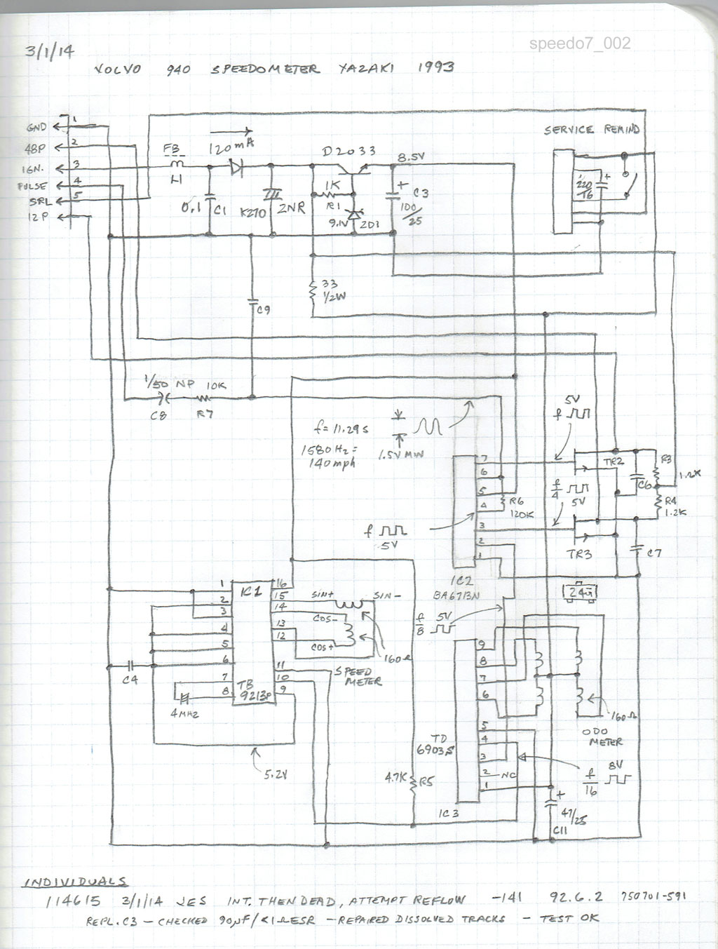
Dave, I had corresponded with OP off list suggesting he might want to verify the wiring back to the sender, but couldn't offer any practical suggestions for the 940 with wire colors to find its termination in the cluster. I think your response is helpful.
In the above drawing from http://cleanflametrap.com/speedo7.html the sender's resistance should be found between terminals 1 and 4 (ground and pulse) as labeled on the meter connector.
Not sure how practical this would be to access, but one would expect the resistance reading to be very close to that of the sender's coil. I also discouraged him from trying to measure the output voltage from the reluctor with an AC voltmeter because the results can be misleading.
--
Art Benstein near Baltimore
"When you sit with a nice girl for two hours, it seems like two minutes. When you sit on a hot stove for two minutes, it seems like two hours. That's relativity." -- Albert Einstein
|
|
|
|
|
Hello Dave,
Thank you very much for your kindness in responding to my post. I immensely appreciate it and am greatfull. For your information, the attached link is the 1993 Volvo 940 Wiring Diagram.
http://www.autoelectric.ru/auto/volvo/940/1993/940-93.htm
I will proceed with removing the instrument cluster to investigate potential problems.
Best regards,
Habib
|
|
|
|
|
Hello Habib,
Here's the info to troubleshoot the speedo wiring
Give an email address and I'll send the Instrument cluster and speedo
schematics.
Here is the outline:
Connector D (5 pins) Harness to sensor
1 Sensor Speedo (GN-W) to C1 pin 12 to speedo sensor pin 2 (GN-W) +
2 Sensor Speedo (BN-W) to C1 pin 11 to speedo sensor pin 1 (BN)
3 Ground (BN) to 31/31 (gnd buss in fuse block) - 31/10
(Ground by passengers right shin)
4 Supply 15+ (BL-R)
Connector C1 is in the dash harness near the driver rear view mirror
Connector D Instrument Cluster
S- to D2 Note: has unknown series component
S+ to D1
+ to D4 series fuse 11/41 (common to speedo, fuel, tach, temp gauges)
Ground via Connector A:2 (Br-GR) reference ground Left A post
(Connector A (8-pin)
You can look for a faulty spread open pin at Connector D
Or a break in the circuits from the connectors to the speedo pins
If there are any tracks that go to a through hole pin and a track on the back side of the flex card and out again through another through hole connection.
be aware the solder connections can be ratty, requiring a jumper tacked onto the
top of the flex card.
Look at that mystery series component S- at D2, what is it?
See if it has gone open with your ohmmeter.
To fix a chronic dead fuel gauge here I found an loose instrument cluster connector pin from the fuel sensor, AND a bad solder joint at a through hole on the instrument cluster flex board that required a jumper.
Look at the flex board circuit tracks and connectors first.
I hope this helps, Bill
|
|
|
|
|
Hi Habib
The link you have for the '93 manual is only for the LH 2.4 pages of the wiring diagrams. You will want the full 200+ page manual. Search for the TP numbers I gave you. I've edited my post to include the relevant pin numbers for the instrument cluster to help you diagnose without the manual.
|
|
|
|
|
Dear Habib,
Hope you're well and stay so!! Before trying to separate the the speedometer wiring harness connector from the sensor in the differential cover, soak the connector with PB Blaster, Kroil or a similar penetrating oil.
These oils need time to work their way through micro-channels in the corrosion, and so weaken the corrosion bond. Repeated soakings at daily intervals is helpful.
If the wires no longer are connected to the harness connector's contacts, you'll need to remove the contacts from the sensor's round pins. Here, too, use of a penetrating oil will help.
To grip the contacts, you'll need a needle-nosed pliers with a 45° or a 90° bend at the tips. Grip the contact and try to turn it slightly, rather than trying to pull it upwards. With persistence, the penetrating oil will allow you turn the contact - breaking the corrosion bond - and then to remove the contact from each of the pins, by turning the contact, and gently pulling on it.
Once that's done, you'll need a short section of wiring harness with two-pin round connectors and a connector housing that fits into the sensor. Each wire of the replacement wiring harness will have to be spliced onto the factory-installed speedometer wiring harness. I'd slide heat shrink tubing over each wire, solder each wire of the replacement wiring harness section, and then apply heat to the heat-shrink tubing.
Once that's done - and your verify that the speedometer works properly - get some butyl rubber tape (auto glass stores likely have this item), and wrap this tape around the end of the wiring harness and the sensor's top. Overlap each turn.
Butyl rubber is very sticky and remains flexible for many years. With finger pressure it can be shaped into a protective "boot" to protect the wiring harness connector-sensor area. This will keep water from again damaging the wires.
Hope this helps.
Yours faithfully,
Spook
|
|
|
|
|
Greetings, Spook,
Thank you so very much for your help. I will follow your recommended process. Again, thank you for being so gracious, as always.
My very best,
Habib
|
|
|
|
|
Although I don't expect it, double-check there are no OBD codes at the diagnostic connector, even if the Check Engine light isn't illuminated. The procedure is in the FAQ. On connector A, port 2 (fuel system) you're looking for code 3-1-1 (Speedometer signal missing). If not then the problem can be assumed to be at or in the instrument cluster and there should be no need to test for a signal from the sender.
There are two sections in the FAQ that address speedometer failures such as yours: in the Electrical:Instruments section and in a feature article on Speedometer repair in the Descriptive file section, also an instrument cluster repair article there. The fault will often be a poorly seated or oxidized connector or a damaged flex circuit board. Have you had the cluster out recently or done work under the dash? There is a known issue with a bad (shorted) capacitor in the Yasaki instrument clusters that can cause speedometer and odometer failure. It's listed for the 1990-1992 700/900 series, so it doesn't appear to affect your 1993 cluster, but you should still be aware of it.
The procedure for getting at and removing the instrument cluster in 940s is in the FAQ. Examine closely the pic of the side clips that you need to bend inward. If you have trouble removing the black metal bezel to get at and remove the cluster then post back for additional tips. There should be no need to do it from underneath the dash. Be extra careful not to scratch the bezel. The bezel and the side clips are very sturdy.
--
Dave -still with 940's, prev 740/240/140/120 You'd think I'd have learned by now
|
|
|
|
|
Hi Mr. Stevens,
Thank you so very much for taking the time to share your thoughts. I really appreciate it.
Best,
Habib
|
|
|
|
|
I do not have a great deal of experience with the electric speedos but the speedo section is solely electric while the odo part relies on mechanical gears as well--a common trouble spot. Since the speedo can work even if the odo doesn't--if they stopped working at the same time--I'd look first at the wire connections at the differential. They are VERY exposed and a source of trouble. - Dave
|
|
|
|
|
Dave,
Thank you very much for sharing your thoughts concerning the subject matter. I very much apprecite it,
Best,
Habib
|
|
|
|
|
YOU ARE CORREEECCCTTT SIR!!!
|
|
|
|
|
YOU ARE CORREEECCCTTT SIR!!!
|
|
|
|
|
Hello Art,
My Volvo 940 terminal connector to the speed sensor is in perfect shape. I removed the speed sensor, tested it, and it registered good resistance. However, I discovered that the wiring going to the sensor has no voltage. Any chance you could share with me of any specific reasons why electricity is not reaching the sensor? Before taking out the instrument cluster I am reaching for the cause.
Best,
Habib
|
|
|
|
|
Hello,
Thank you for taking the time to respond to my inquiry. The problem happened to be the corroded capacitors on the speedometer that have been fixed.
Regards,
Habib
|
|
|
|
|
Hello, Art.
Thank you so very much for the pictures and the tips. I really appreciate it.
Best,
Habib
|
|
|
|
|
©Jarrod Stenberg 1997-2022. All material except where indicated.
All participants agree to these terms.
Brickboard.com is not affiliated with nor sponsored by AB Volvo, Volvo Car Corporation, Volvo Cars of North America, Inc. or Ford Motor Company. Brickboard.com is a Volvo owner/enthusiast site, similar to a club, and does not intend to pose as an official Volvo site. The official Volvo site can be found here.
|


