|
Low Coolant Sensor Light (LED) Alarm
Using info gleaned from the 700/900 FAQ’s I fashioned an LED light alarm that will warn me of a catastrophic loss in coolant. I’ve read several posts on the Brickboard over the years where heater hoses have ruptured, or radiator necks have broken spewing coolant quickly. By the time the redlined temperature gauge is noticed, it is too late and warped head or other engine damage has occurred. This easy, approximately $25 2 hour project can save you from that horror with a warning light when the expansion tank empties of coolant.
Parts required include:
Liquid Level Sensor – McMaster Carr Part No. 50195 K74 - This is a Normally Open Switch
Radio Shack LED Assembly (Red) - 276-270
About 10’ of Wire scavenged from the JY along with a few spade connectors.
About 5’ of 3/8” wire sheath, also scavenged (although you can buy it).
Solder and Heat shrink tubing. If you must, butt connectors are OK too.
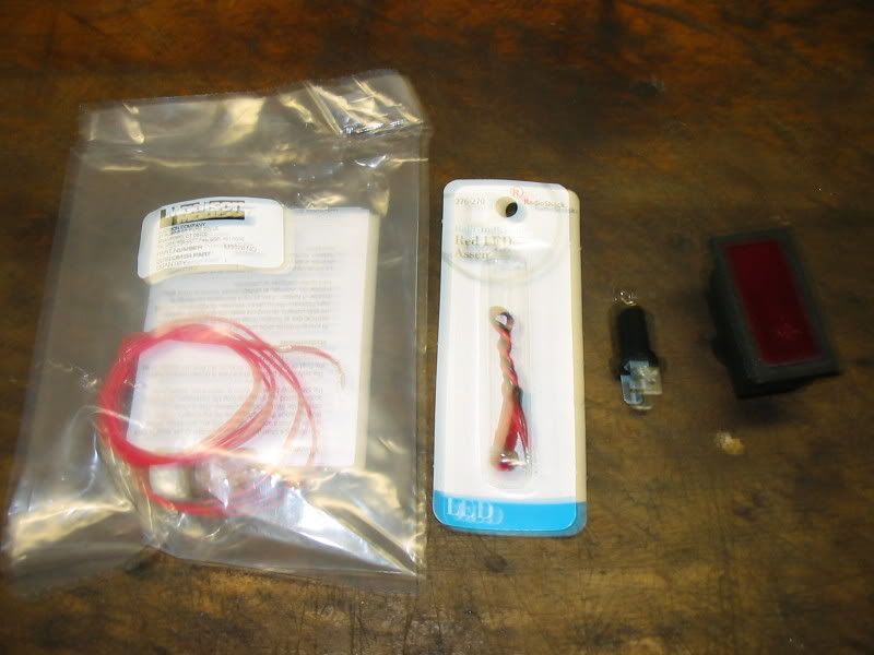
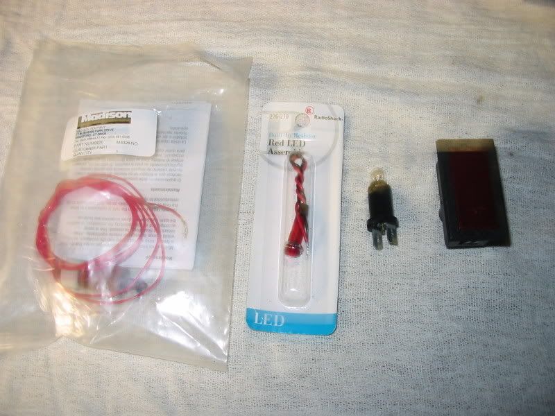
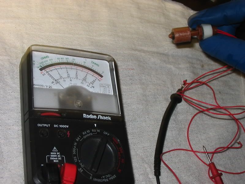
Getting Started: Check out the parts in pictures 1 and 2. You’ll note that I included a seat belt warning light with bulb. Originally, I was going to use that for my warning light with the little white insignia rubbed off. This worked well until the large current requirements called for by the 2w bulb exceeded the current capacity (125 ma.) of the liquid level sensor. Using the LED with only 20 ma draw is within the working capacity of the liquid level switch so I abandoned the 2w bulb approach. The sensor and LED both handle 12v. I did have to purchase a new switch, however to replace the burnt out one.
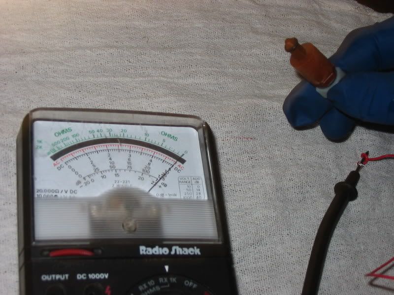
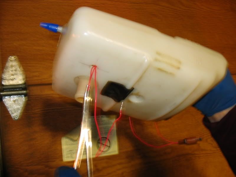
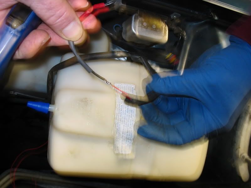
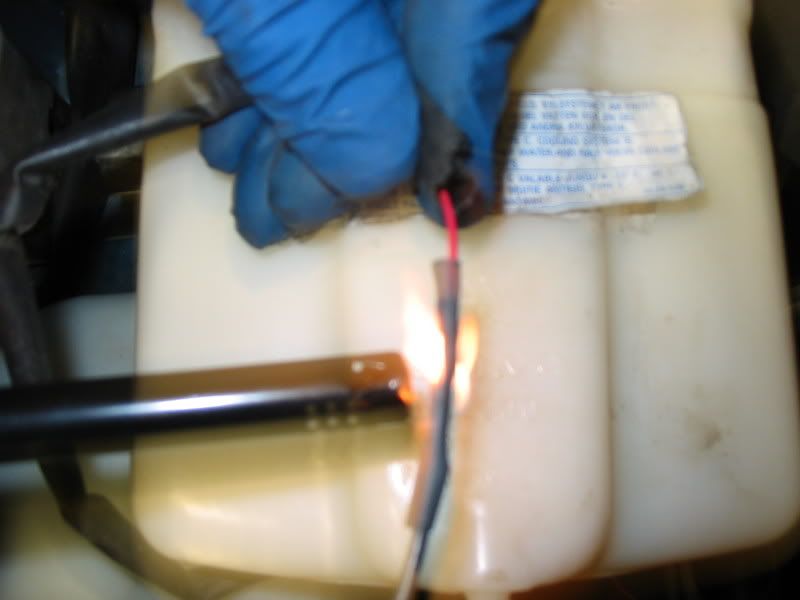
Notice the way the sensor works in Pictures 4 and 5. When the little (polypropylene) float is up, there’s infinite resistance (no continuity), but when the float is down, as it would be after a loss of coolant in the expansion tank, there is no resistance and a circuit can therefore be completed. Incidentally, this is called a normally open circuit.
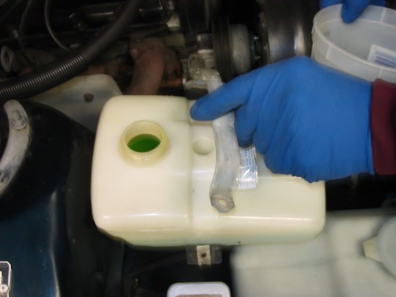
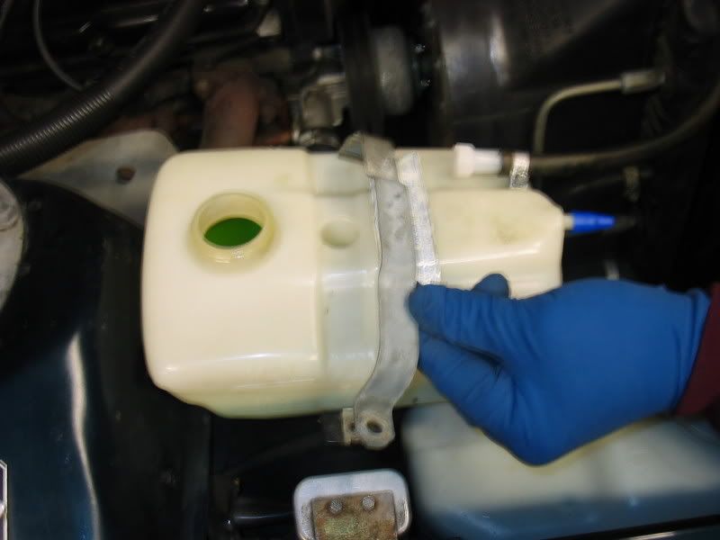
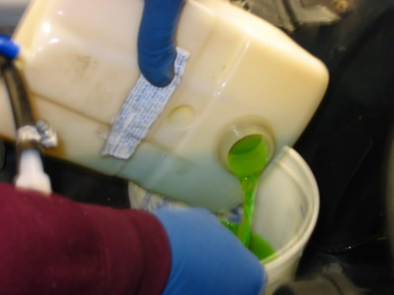
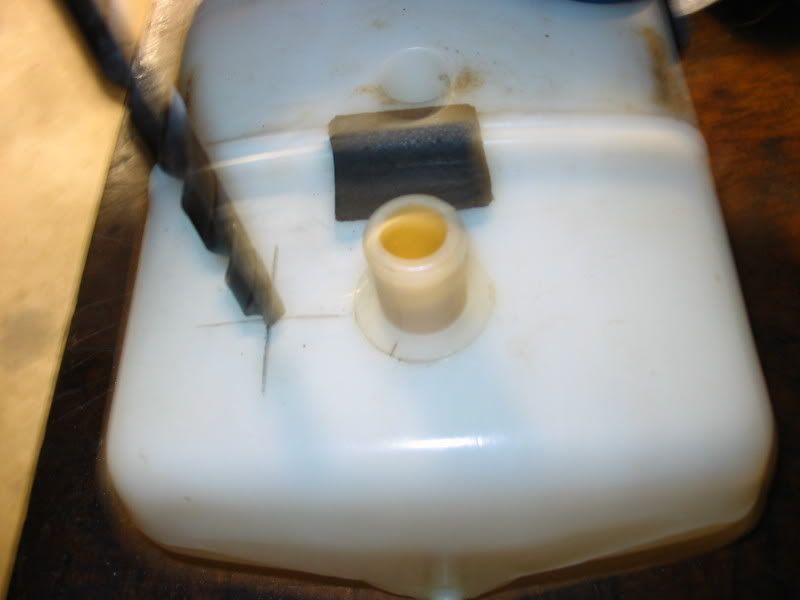
Picture 6, 7 and 8 show removal of the clamp for the coolant expansion tank, and the use of some plugs on the rubber line and barb to keep the mess to a minimum. You can easily pour the coolant into a temporary container, to facilitate coolant tank removal.
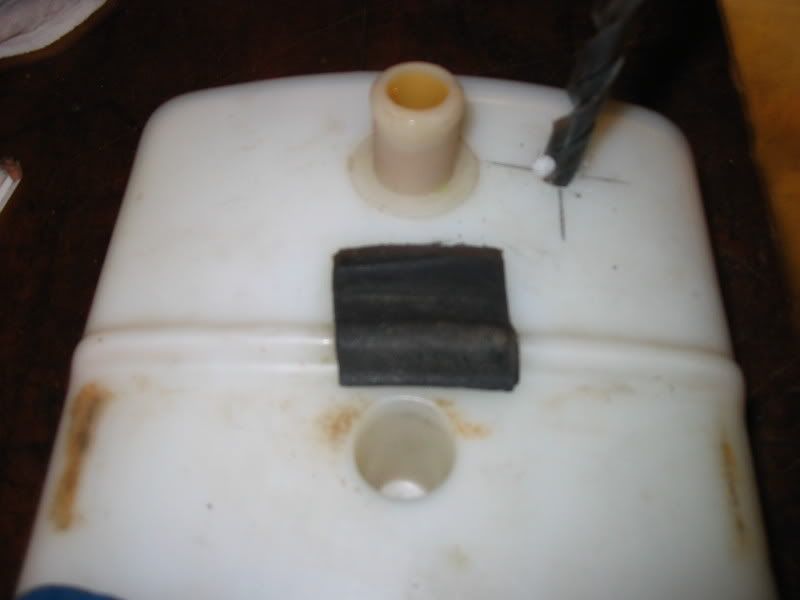
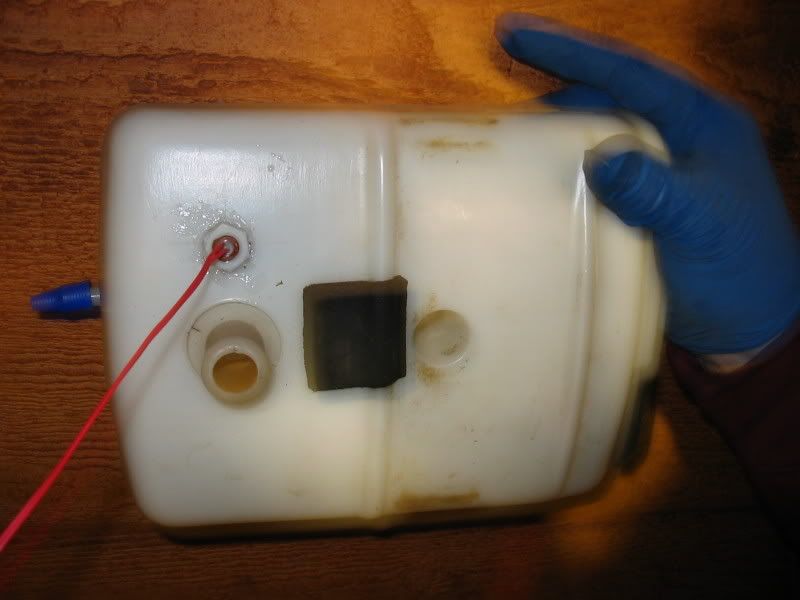
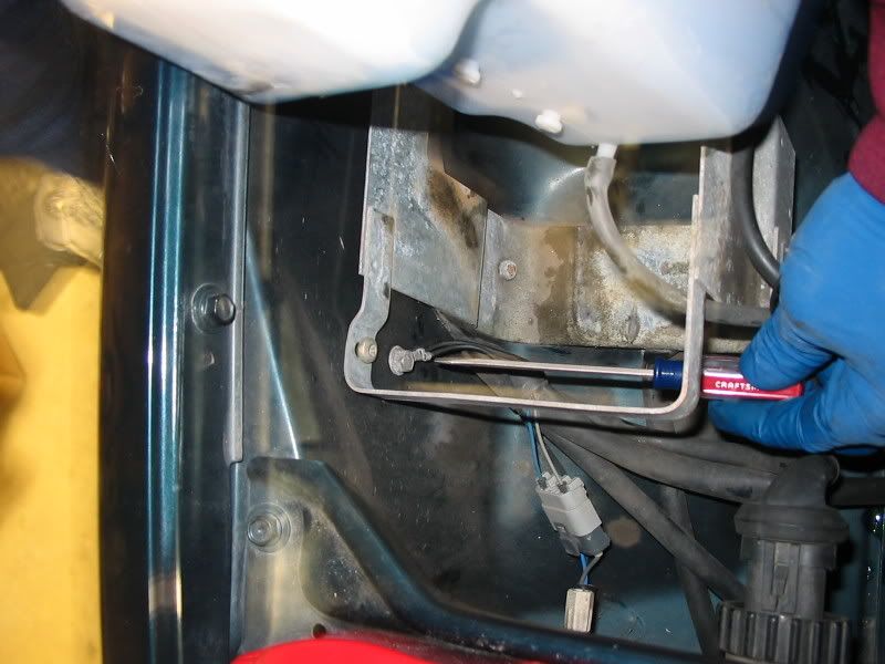
I elected to install the sensor (which hangs down a little below the tank) at the location shown so as not to interfere with the bracket underneath that supports the coolant expansion tank. This location shown in Pix 9-12, however, hampers your ability to “play” with the sensor float, except with a coat-hanger or wire probe to manually position the sensor float to check the operation of your sensor. If you elect to install the sensor closer to the fill hole, you will have to ream a hole in the bracket below. In any event, the sensor
requires a 3/8” hole that you will have to fish the sensor wires through. The sensor comes with an o-ring, which is installed inside the tank. I also installed the sensor with a little silicone seal on the outside before I snugged the plastic shaft nut down.
Pictures 13, 14 and 15 show that nice ground screw that I’m pointing to behind the windshield washer tank. The tank just pulls up enough to expose that screw, which you can use to make one side of the sensor connection. I used some of the 3/8” wire sheath I scavenged from the JY to enclose, at least as far as possible some of this ground wiring. To make connections neat, I used heat shrink tubing with soldered connections.
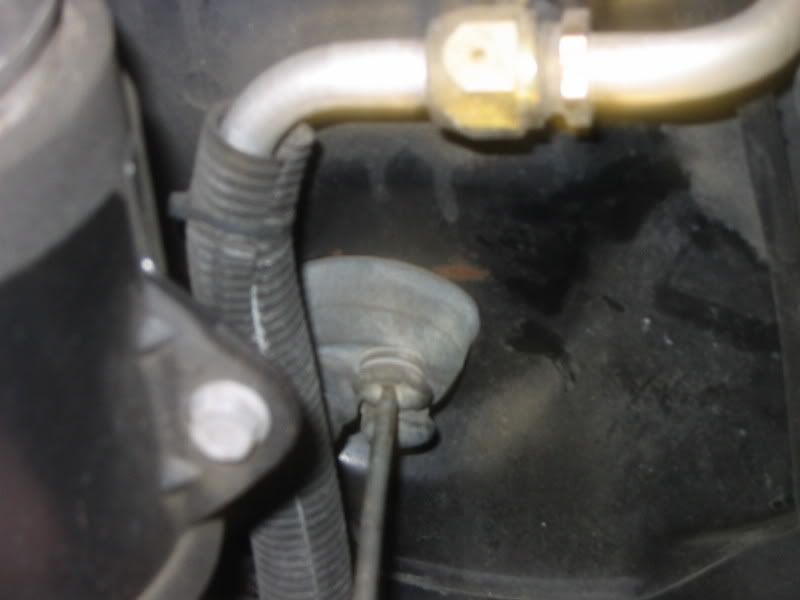
The other leg of the sensor needs to run all the way to the dash opening where the dash blank is. There’s a nice little grommet shown in Pix 16 that I’m poking with an awl to make a small hole for the wire to pass through. I wouldn’t make that hole too big, as the rubber seems to close up nicely around the wire. I also used wire sheath from the firewall to the other sensor lead and a few well-placed zip ties. Keep in mind that you will need to remove the glove-box to enable you to fish these wires through to the dash blank slot. Incidentally, the dash blank (See Pix 19) just pops out with some gentle prodding with a small screwdriver.
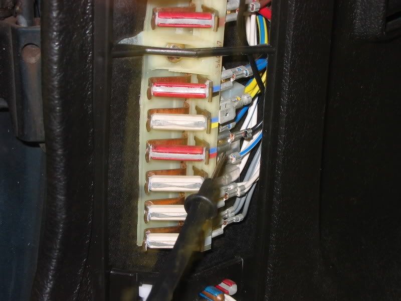
Now it’s time to obtain power from the fuse panel. Remove the fuse panel cover and use a 12v test light or multi-meter to find an open spade where it is only live when the key is turned on as there is no need to have power available to the alarm when the car is off. On my 93, fourth circuit from the bottom shown in Pix 17 was the 16a circuit that controls the seat belt warmers, only energized with the key on position 2. The black wire that I’m pointing to with my meter probe is what I used to run power (I’m not particular about colors since I label all my wires) to the LED. I would recommend that after you determine which spade you will use, you disconnect the ground side of the battery as you continue to fiddle around with the fuse panel.
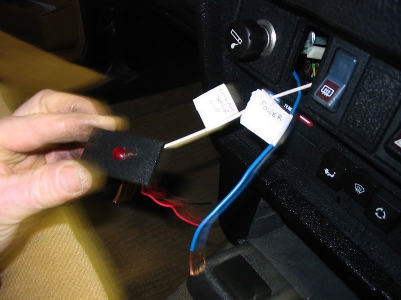
Make connection to the spade and fish your wire up behind the dash above the steering column (I don’t think you need to remove the instrument cluster) and feed it through the dash blank slot. To “see what you are doing”, you will likely need to remove the underdash panel, and on later models the knee bolster.
Take the dash blank and on your work bench, mount the red LED wherever you want it. For me dead center was fine. You can use connectors that are removable when you connect to the wires now protruding from the dash blank hole, or solder your connectors as I did with heat shrink wrap. To install the LED, I used my soldering gun to melt a nice starter hole in the dash blank that I further reamed out slowly with a small file. The LED comes with a lockwasher and nut. One important thing to remember is that the LED red lead must be connected to power, black to ground. Flip those wires and the LED will never work. Don’t ask me how I know.
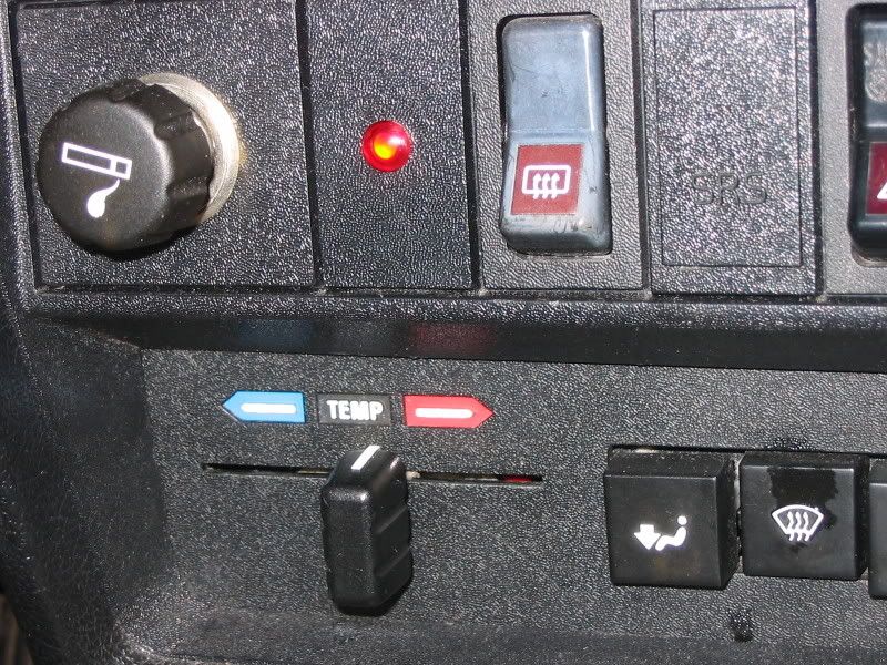
That’s it. Reconnect the battery and check the operation of the system by turning the key to position 2 and inserting something into the coolant jug to push the float to it’s down
Coolant Sensor Alarm System
position. For the first few weeks, I’d carry around some antifreeze and water, just in case you’ve screwed up and have a leak.
I also again want to remind you is it’s nice to be able to look into the coolant expansion tank and see the sensor float but that position requires some cutting or drilling of the coolant bottle support bracket. I think on my other 93, I will cut the bracket to enable sensor installation at a location where I can view it through the fill hole.
The last thing I would ask is that if someone knows how to create a nice little sign or note to paste onto the dash blank that says: “ DANGER LOW COOLANT” that fits permanently or semi-permanently on the dash blank, I’d be much obliged.
|