|
Hiya Uncle Old Duke!
Your message appears forlorn for some days. This is our Uncle Art's domain as you can read here:
http://cleanflametrap.com/speedo.html
A small punch, so, like to slap the dash cap above the speedometer dash head assembly thingy, and the speedo / odometer again works for awhile?
It could be that the speedo cable wire connection at the back of the speedo is loose. You can pull the knee bolter and the felty thing and reach up. May be easier to remove the steering turn signal-wiper stalk box top cover, the headlight switch assembly, the small clock-square bezel covers to the right, and then remove the hardware securing the dash head speedo box out.
Do you have any other problems simultaneous to the speedo not working that is also treated with a punch or slap to the dash? What do you actually hit.
I'd found the large connector posts, like the round and half moon connectors can get broken solder welds around them on the green inner side of the large PC board backing the whole assembly. I'd soldered these as part of the faker board by pass wire up.
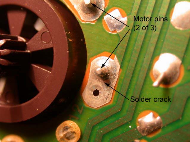
Also, on the green 1992 240 (yours is a 1992 240, yes? I know it has the three pedals!), the speedo motor signal and stepper board, to which the wire harness speedo cable wire connects, as our Uncle Art shows here:
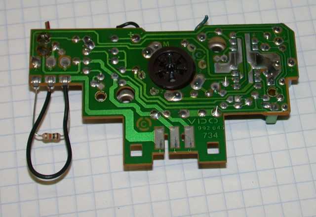
... had broken solder welds. Using a Jeweler's Loupe (like a monocle magnifying glass), with a not too hot soldering pencil, I reflowed solder on this board. Though my hint was:
https://www.brickboard.com/RWD/index.htm?id=1409651&show_all=X
OBD box socket 6 code 3-1-1 with the high RPMs after exiting the highway.
The gears were fine, yet the ODO does not work. Speedo work fine. So, I have to pull the dash head sometime. I'm being lazy.
The vehicle speed sensor is mounted on the rear differential cover. You can test the sensor and the connecting cable with at the cable connector that secure to the speedo board. Though forget which of the three contacts you would test for continuity. Dunno ideal resistance values using a nine volt powered multimeter.
On that speedo cable wire, two of the contacts / wires come from the differential mounted speedo sensor.
One contact / wire goes to the engine control for the Bosch EZK ignition and the cruise control. Though unsure whether separate wires come out of the speedo dash head - 1 to the engine control, another to the cruise control, if fitted.
PDF Page 23 of 23 in the 1992 240 PDF.
http://www.volvowiringdiagrams.com/?dir=volvo/240%20Wiring%20Diagrams
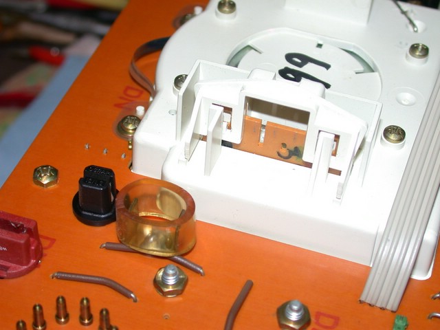
The wire that connects to the speedo for the cruise control is a two spade connector that usually ahs a piece of hose around it, I believe. In Uncle Art's image here, it has a clear piece of flexible PVC.
Be careful when reconnecting the wires. Some people will leave the keys in or the battery connected whemn doing this work, and they'll connect a 12 VDC wire to the picture lugs, and will dry the speedo / odo vehicle speedo sensor signal processing board.
Does that help, I hope?
I'm Uncle Art can clear up the muddies waters fomenting this reply for you.
Though the issue is treated detail in many threads here, if you can find them using the search feature.
Oh, yeah, no, the engine control systems use the electronic speedo. It's all integrated. To fabricate some sort of integration to a mechanical speedo would be a bigger PIA, I guess.
Happy Eggnog Holidays!!!!
Questions?
Hope that helps.
Mac and Cheese Duff.
--
Give your brickboard.com a big thumbs up! Way up! - Roger Ebert. 
|