|
|
|
At the advice of counsel I am starting a new thread.
I have a 1885 244 that will cough a bit when cranking, but won't start. After a couple months of weekends checking the wiring and connections,changing the ECU and ICU,and a side trip replacing my slipping crank pulley, timing and accessory belts, and (for good measure) the water pump, This thread is a case study of my attempt to follow troubleshooting procedures for the LH2.2 fuel injection system on a 1985 B230F. (Paraphrased help from Art Bernstein is included below.)
What I'm trying to fix now: A no start condition.
Engine cranks (and occasional coughs). Fuel in fuel rail, spark at plugs. Assumption: Fuel injectors are not injecting.
I'm using the Bentley Manual, "Checking Main Relay" p. 241-11. Using a test lamp in the harness connections to the System/Fuel relay.
Step 1: Check 87/1 and 87/2 for voltage when cranking? -- Yes, voltage is present at both of these terminals when the engine cranks.
Step 2: The yellow/black wire goes to 86-1 which is the system relay coil. It needs a ground from the computer to keep the system relay pulled in. The purpose of this circuit is to keep the fuel system active for the amount of time it takes to deliver the burn-off current to the AMM's hot wire. The test is done with the ignition switch at Key Position 2 (KP-2. A very low/no voltage condition when the ignition is energized is required for the engine to run.
Test result: No voltage.
|
|
|
|
|
Hi,
I’m trying to follow on the new post to what you are doing to get this car running with injectors.
I assume the car runs a little bit on starting fluid if you tried this during all the other postings.
That test proves timing and spark is there and the car will run if the injectors opened.
You can also wrap a rubber band around both of the contacts arms and bypass the ECU to see if the car will run through the relay.
There is one other tricky thing that you might be missing when using a test light or a voltmeter, that I still like best when messing around the ECU’s for protection.
When using either tool you need to remember that you have to be ACROSS the line of potential voltage in order to read voltage.
In other words, you cannot expect a reading if “both leads of the tool” are on the same side of the battery.
There is an exception to this voltage testing idea but only if you are looking for some type of very high resistance on a ground circuit side but that is only another test not involving your troubles as you are not working at all.
I had this old post of Art Bensteins on a 1985. I kept it tagged in favorites for my 1986 wagon showing the relay wiring. It’s still LH 2.2.
https://www.brickboard.com/RWD/volvo/1636835/220/240/260/280/now_issue_fuel_injection.html
He made corrections on it or added clarity depending on your amount of fuzz one has.
I think this shows what you need stretched out flat.
The notation he made “system relay” are the fuel injectors.
It is fed power from the red wire to actually power on the injectors when ever the ECU grounds them.
The Yellow/black is like you say, the grounding wire. It is used to energize the coil to pull in the contacts for the red wire to do its job.
In all this looping of connections is where the orange wire jumps into the mix. You can read that orange wire under the AMM connector rubber boot. Then you know the injectors are hot with power.
The reason you might not be getting a reading on that grounding wire Y/B is you are not ACROSS the potential of the battery circuit. From what I can tell from the instructions it does not tell you what you have to do to get that reading with your measuring tools.
They assumed that the technical person looking at their manuals have some understanding of electrics. As we all find out “we do not” as it’s part of the “knocks on the head” of getting educated.
Phil
|
|

|
|
Hi Phil,
I know you don't mind me helping you.
"I assume the car runs a little bit on starting fluid if you tried this during all the other postings."
You assume more than I do. I don't recall this being part of the troubleshooting.
"That test proves timing and spark is there and the car will run if the injectors opened."
Not quite. The injectors can open, but if the "fuel at the rail" OP claims is at atmospheric pressure, where's the fuel gonna go? Could be the injectors aren't opening, but then how is it coughing and spitting? Vacuum pulling fuel in past closed injectors? Through a holey FPR diaphragm?? No, I don't think the assumption that the injectors aren't working is convincing. How about checking fuel pressure?
"You can also wrap a rubber band around both of the contacts arms and bypass the ECU to see if the car will run through the relay."
OP's test showed there was battery at both 87/1 and 87/2 which Michael found during his execution of "step 1" of "To test main relay" on 241-11 of Bentley. Step 1 says "If either terminal has no voltage, go to step 2." In his last thread I asked why he was doing step 2 at all, but there was no answer. The relay is OK. In fact that's exactly the wording in the Bentley. "The relay is OK."
"When using either tool you need to remember that you have to be ACROSS the line of potential voltage in order to read voltage. "
This is true, like when you try to verify a contactor's coil is being energized, but in Bentley's test (step 2 where one tries to troubleshoot a relay that is NOT OK) they are looking for a voltage referenced to ground by asking to check for "battery voltage." Not for a lighted test light. But their troubleshooting steps 3 and 4 are in error, which I believe we identified in the Bentley Errata list. However it is moot, since "step 1" already verified the relay didn't need troubleshooting.
The devil's in the details. The paraphrasing OP did doesn't accurately represent Mr. Bernstein or Mr. Bentley, and the assertions of "spark at plugs" and "fuel in the rail" don't lead me to assumptions like "Fuel injectors are not injecting."
Yet, if I were to read "fuel pressure is 43 psig" and "the 'noid light remains dark" I'd ask about what that 1985 engine harness looks like. CB suggested the problem solver hinted at ECUs having a reputation for losing injector driver transistors, and if so, with the LH2.2 boxes, I'd guess this could be why.
--
Art Benstein near Baltimore
Always keep your words soft and sweet, just in case you have to eat them.
|
|
|
|
|
Hi Art!
Yes you are correct I don't mind you helping me. At any time I'd rather be helped than have to Yelp for it! (:-)
Oh yes, you and I are right, the devil is in the details. Especially for you, because you cruise in that neighborhood all the time.
For me, I just drive around a lot and sometimes crash but luckily I have Angels like you on my shoulders.
I will admit I do try to kiss (Keep It Simple Stupid) things off for not being as not so complicated as they can always appear to be in this world.
I probably didn't help his situation by telling him to check out the timing of the engine either. I brought up a convincing possibilities by bringing up the idea of the physics triangle of rapid oxidation. Air and fuel needs a little heat. Diesels and gasoline engines get their heat one way or the other but it's all timed.
Little did I know, he would tear into the whole car and spend a few weekends doing all the work he did do. Guess he had the time and maybe it was time for some TLC.
From what I can tell from the picture and posts he is doing a great job!
I admit a little slow and long for us!
But hey, that what keeps these cars alive to do what they were built for and a BrickBoard.
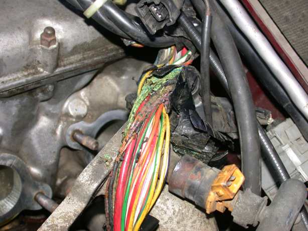
He said he went through the wiring covers under the engine but it's true he might still have a rats nest like your picture very adequately shows.
I was suggesting my short cut ideas to get him off the relay hunt!
His last post frustrated him and asked for explanation or some reason for the no voltage signal. He is getting, All of this, from our armchairs!
You are saying no fuel pressure and or wiring. I just want to know if it will run at all, especially, after all the work done. Frustrations can go a long ways to stop the hands from working.
Getting a pressure gauge onto that rail is a process.
I know because I silver soldered my own Schrader valve onto my fuel rail shortly after getting the car. I never gave it a thought of pointing it downward.
Definitely Not like Volvo did with it point down onto the engine to keep down a possible big fire!
I don't know why Volvo did what they did unless to sell adapters to the dealer parts departments.
You can get refrigeration hose adapters to make that turn but how many owners know that and have refrigeration equipment and want gasoline in their hoses.
Whoops! I have done that! Both are petroleum products and a good vacuum takes care of that! You got gauges and hose why not? They deal with liquid and vapor pressure just like any other Bourdon tube gauge.
There I go again, I kissed it!
Thanks for pointing out the details, again, it's all good food for thinking about!
Phil
|
|
|
|
|
for I-5, as if we were trying to help one of our own sons or daughters to get their daily driver back on the road. Lets keep it as simple as possible. I'm glad he didn't go for changing the shaft seals on this go-round.
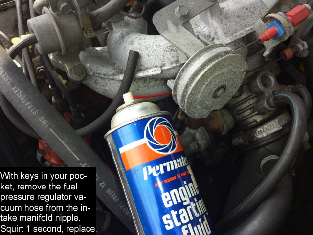
I will start by assuring ourselves of that spark + timing presumption, and ask I-5 to buy a can of starting fluid, connect a straw to the valve, and inject 1 second's worth into the vacuum port used to compensate the fuel pressure regulator. Not into the regulator, but into the manifold. 1 second. Then crank and try to start.
We'll get to the fuel rail pressure and injector operation afterward. I have a feeling I've already told you my tale of using a refrigeration tap to make a fuel pressure gauge adapter.
--
Art Benstein near Baltimore
We childproofed our homes, but they are still getting in.
|
|
posted by
someone claiming to be CB
on
Tue Nov 13 23:05 CST 2018 [ RELATED]
|
|
"you can lead a horse to water, but......"
You can show a Librarian a book, but you can't make him read it.
Volvo Prob Solver Section 25 XXXX LH 2.2 System
p 25 011
mid page-- Fuel Inj Control Unit---
There are very few bad control units, they do occur BUT THEY ARE RARE. The most common problem... is that it will not provide the needed ground for the INJ Relays to Turn ON.......
SEE FuInjRel TEST in the BASIC CHECK GRP........
and there's more
ENTIRE Section 25 - XXXX
LH Jetronic
25-111 LH 2 F-Inj Relay terminals --- diagram and list of Whots HOT and Whots Grnd and (short list) HALF A PAGE
And
Sect 11-051 FI Relay testing 1985-on BASIC CHECKS
7-271 LH Jetronic 85-88 Poor Running
Oh what no color Pix????
Diagram on 11- 501
Ignition Important Cnxs and Areas(locations in Engine Bay):
C)-85-on Cnxn for Ign Signal to F/I (under /manifold)
|
|
|
|
|
My 88 240 had a run fine then die issue that turned out to be the Ignition Control Module. When I replaced it with an old one I had saved from a former 240 it started and has not left me stranded since. It mounted on the passenger side up near the radiator. They are on eBay or you may find one in a bone yard. Prior to finding the problem, I had replaced many many parts withOUT success.
|
|
|
|
|
Hint: You can proofread and edit your posts for about an hour after posting them.
--
Art Benstein near Baltimore
A skeptical anthropologist was cataloging South American folk remedies with the assistance of a tribal Brujo who indicated that the leaves of a particular fern were a sure cure for any case of constipation. When the anthropologist expressed his doubts, the Brujo looked him in the eye and said, "Let me tell you, with fronds like these, you don't need enemas."
|
|
|
|
|
"Hint: You can proofread and edit your posts for about an hour after posting them."
Thanks Art!
|
|
|
|
|
Dear Phil, Art, CB, et al,
I had a tough week at work and forgot about the car for a while. Then I come back and find all this help waiting for me. Apropos the season, I am thankful.
Phil, I didn’t know about the starter fluid test. Art’s picture and directions will make it virtually impossible for me to screw it up. I will do the test tonight and report the result.
Phil: The reason you might not be getting a reading on that grounding wire Y/B is you are not ACROSS the potential of the battery circuit. From what I can tell from the instructions, it does not tell you what you have to do to get that reading with your measuring tools.
I need to understand this. Good point.
Phil: They assumed that the technical person looking at their manuals have some understanding of electrics.
That seems like a fair assumption. Would that it were true in my case.
Art: "spark at plugs" and "fuel in the rail" don't lead me to assumptions like "Fuel injectors are not injecting."
Good point. I have no idea if the fuel pressure is adequate for injectors to function. But with spark and compression, I thought that if the injectors were injecting the car would run in some fashion. And I didn't feel any injector pulses through my screwdriver on the injector bodies when my friend cranked the engine. On my 245, I feel these pulses distinctly.
Art: I have a feeling I've already told you my tale of using a refrigeration tap to make a fuel pressure gauge adapter.
I would like to learn that twice told tale. It sounds like a useful modification.
Phil, you are right in noting that I am so slow to make progress. I have a kid to raise, 2.5 hours a day commuting (in a 245), and 50+ hours a week at work. But I am slowly learning a little about how my car works. This is interesting. It makes me feel good about myself. It deepens my long held appreciation of old Volvos. I am confident that by putting the advice and the information provided here to use I will have earned the right to be driving my favorite car again. Eventually.
Phil: He said he went through the wiring covers under the engine but it's true he might still have a rats nest like your picture very adequately shows.
I don’t think so Phil. Everywhere I look, poke, probe, and clean, the wires all seem to be ok. They appear to be physically sound with no signs of deterioration. However, as you know, I am often wrong.
Art: I'm glad he didn't go for changing the shaft seals on this go-round.
It was hard not to, with them right in front of me. But I trust good advice.
CB, you are right. I did not read the Volvo Problem Solver book. It intimidated me, and with all the pages I’ve printed and the Bentley manual I’ve been looking at sporadically, I blanked out a bit. That is, until you gave me the specific sections to learn. I will print these out and study them carefully. Thank you. The hardest battle for me is psychological. Believing that it is possible for me to do the job is the toughest part.
Bill N, thanks for sharing your good luck in replacing the Ignition Control Module (ICM) on your car. I appreciate the suggestion. In my case, I got a spare at a junkyard and swapped it in, but there was no difference. I wonder about that long problematic vacuum line coming out of it and snaking all the way to the other side of the engine…
|
|
posted by
someone claiming to be CB
on
Mon Nov 19 20:59 CST 2018 [ RELATED]
|
|
""""CB, you are right. I did not read the Volvo Problem Solver book. It intimidated me, and with all the pages I’ve printed and the Bentley manual I’ve been looking at sporadically, I blanked out a bit. """
Yes that is the problem with the VPS book---it's one of those that dosen't translate well into digital views.
It orig came in a looseleaf binder with a number of plastic sheaths included, so you cud pull out the pages that pertained to the particular issue being worked on and not grease them up.
Old Teck.
I had Haynes, Bentley,, which covered so many configurations.
Then I got this and just pulled the instructions I needed for my problem---Plastic cover---and.
Some think that an iPad with the needed info on the fender is another ticket, but got an iPad U R willing to grease up???
|
|
|
|
|
No luck with the starting fluid trick. Not a cough. So it wasn't the fuel injectors not injecting. My inability to detect injector pulses when cranking over was meaningless.
I go all around checking grounds and so on. Crank it to test several times but no start.
A little before 1am, inspiration strikes. I check the notch on the circular rim of the distributor, below the rotor. It seems to be pointing more toward the center of the engine than I expected. I compare it to the relative angle of the distributor notch on my 91 245. That one is pointing approximately toward the center of the cooling fan. A noticeable difference.
I go back to the 244, loosen the distributor hold down bolt, and try to move the distributor, but it has been set in one spot for years, apparently. With careful tapping and twisting, I finally get it to shift bit by bit, and slowly rotate it counter-clockwise at least an inch.
I crank the engine and nothing happens for four seconds, then the car abruptly starts up. It is idling way too fast, and the idle speed 'hunts' dramatically as the ECU/ICU compensates periodically for some inbalance, but the engine is running relatively smoothly on four cylinders and doesn't stall.
I look and listen to it running for about five minutes. Suddenly steam come shooting out of the engine compartment. I shut it off. The thermostat must have opened and the new water pump is leaking at the joint where the pipe enters it from the back. My mistake installing the new rubber seal, and coolant was pouring out on the hot engine. But it runs.
|
|
posted by
someone claiming to be CB
on
Sun Nov 18 19:50 CST 2018 [ RELATED]
|
|
as posted to you in your other thread about the leaking seal WaterPump Pipe.
You Do not need to remove the Water Pump fix the seal...If the Seal is torn you just need a new seal.
posted by someone claiming to be CB on Mon Nov 5 17:36 CST 2018 [RELATED]
Re WaterPump seal. OOPs
That pipe that runs fromback of the WP runs
under the exhs manifold and to the back of the engine - goes cnx with the heater hose.
Under #4 Exh that pipe has a bracket that is bolted into the block --- 13mm if I recall. Need to use a closed end wrench. Take out the Bolt and free the pipe from the block.
The WP mounting procedure is to undo the bracket freeing up that pipe. The hose will let you move the pipe around a bit.
In your case, just fixing the leaking seal...pull the pipe from the back of the water pump. if the seal stays in the pump pull it out.
You then put the seal on the pipe and insert the pipe into the back of the already mounted WP. That way you don't pinch or twist the Seal pushing the WP onto the rigidly held pipe.
|
|
posted by
someone claiming to be Eye5
on
Sun Nov 18 23:05 CST 2018 [ RELATED]
|
|
Thanks CB. That is really helpful. I was going to pull out the water pump.
|
|
|
|
|
Hi,
I was afraid of this happening or getting missed.
When I was trying to study your pictures things just didn’t set well with me.
I made a post with my concerns here.
https://www.brickboard.com/RWD/volvo/1659853/220/240/260/280/1985_244_run_yet.html
That plastic mark for timing the distributor is somewhat allusive. Darn hard to describe where it’s located on an leaning engine.
I could almost see the distributor pointing off in the wrong area by looking at the surroundings and I questioned at what phase you were in timing the engine in a picture.
Darned armchairs are just to far away at times!
Art is probably right about moving the distributor to get it to run and the timing is still not right.
When things are right, the bolt should be pretty much centered in its slot, so it cannot be shifted so far out of timing. Does the bolt tighten up back in its hole and still in the slot?
Being that the distributor was so hard to turn, means it had not been out in a long time. A harden O ring and aluminum in the cast iron block doesn’t help.
So sorry that the dot below is not aligned.
Again the little bump in the plastic is hard to see or even feel! Bright light and a mirror is needed when you get back down there when working from above.
In fact, I thought on that year car it was a detent but on my 1990 engine, on my engine stand it’s raised up, so, there may have been a change by Volvo.
A couple or even three teeth spins that distributor a bunch in relation to the width of the rotor contact tip. Thus, the starting fluid vapor only flamed in the cylinder, at best and didn’t get to explode.
Good news is that it will run like before, when you get it right.
If you leave the water pump leaking the windshield wipers won’t squeak with the lubrication of the antifreeze. (:-)
Phil
|
|
posted by
someone claiming to be Eye5
on
Sun Nov 18 23:38 CST 2018 [ RELATED]
|
|
"Art is probably right about moving the distributor to get it to run and the timing is still not right. When things are right, the bolt should be pretty much centered in its slot, so it cannot be shifted so far out of timing. Does the bolt tighten up back in its hole and still in the slot?
When I finally checked the distributor body's orientation I looked at the hold-down bolt. The bolt was tight, heavily oxidized, and not centered in the hold-down slot. It was at one far end of the slot, and had been that way for a while. It does tighten up fine.
I took pains to set all the timing marks correctly. I don't think the timing belt had had a chance to slip. On the 85, the #1 cylinder TDC rotor mark on the distributor body was milled in to the rim of the distributor I think the car would not run because the distributor's hall effect trigger mechanism was very mistimed.
|
|
posted by
someone claiming to be CB
on
Mon Nov 19 20:26 CST 2018 [ RELATED]
|
|
The only way this condition cud have been set up ---- for so long.
somewhere in the Past, when the timing belt was replaced, the gear that runs the distributor...the one on the right of the three that the belt needs to "be on the Mark" was OFF. When whoever, buttoned the thing up and tried to start it...OOPPS/
so rather than rip it apart again and redo the belt, he/she/it/XXXXX/OOOOO/ZZZZ adjusted the distrib timing to get it to run. Fortunately for (not sure of the proper pronoun) there was just enough space in that mounting arc to let that happen.
As to Why, 1)the car started to run poorly for you. 2) it then failed to run/start/sputter as recently as you began these threads.
Odin only knows.
|
|
|
|
|
Hi Mike,
You got me there on the Hall effect sensor, as I have never had to mess with one of those!
I would think it only mounts into the center one way?
The reluctor has to be keyed on the shaft. That might be loose? Look down in there closely for a tiny roll pin!
Don’t know about the pickup coil though. Don’t have a clue how it’s held in there.
Maybe someone else has more information on that.
That milled in, flat notch, is important in relation to the number one plug tower as I remember.
Apparently, when resetting the distributor back in the hole it may be important too?
Something, somewhere was on the wrong tooth!
Don’t remember if the cap uses that particular notch, to sit into, to lock itself either.
Too much time goes on between any tuning up I get to do.
I spread all my driven mileage across several vehicles. I’m just crazy enough to keep the insurance companies straight on how much I do drive each on.
It seems that one or three things were off or something. The timing belt jumped a tooth or two and or this happened before and a PO or mechanic got something wrong the last time.
It helped sell the car to you though as the owner had worries, I’ll bet!
Now you are throwing in the Hall effect sensor movement to add some scrabble tiles to the mix, wow! Trying to make a diagnosis from all this is surely guessing!
At least we know, if the timing get right with it world down there, the car runs ... Thank goodness!
Phil
|
|
|
|
|
Hi Phil, I am going down to the garage before bed and try and reset the leaking water pump gasket using CB's method. While I'm there I can get a couple of distributor photos for you.
|
|
|
|
|
Remember the iatrogenesis? This need to move the distributor, like the dead ECU has a cause in technician error. Most likely it is your error, but there's a chance you can blame it on a previous mechanic.
If the ignition timing is significantly retarded, you can be burning much of the fuel in the exhaust manifold instead of in the cylinders. It will actually glow red. That could be why the motor overheated, but there's an opportunity to make another error installing the seal on the heater return pipe -- one I made.
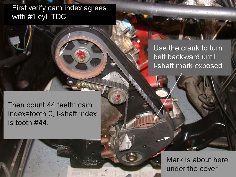
The error is in aligning the I-shaft timing mark, that's the root cause. It is your error if you check and find it is off, but it is such a common error (remember the parallax issue?) it could have been done in previous work, and then compensated by pulling the distributor and re-installing its gear a tooth in the right direction.
1. Install the dry O-ring on the pipe, not in the water pump, then lube its outside.
2. Remove the upper timing cover, turn the crank bolt until the cam mark is aligned. Use a stick to check TDC is exactly where the cam mark aligns. Then carefully count the teeth as in the picture below to check your I-shaft sprocket alignment.
3. Buy a timing light. Basic is best, you don't need one which does calculations, just a light that flashes when you have spark. Don't run the motor long until you have timing set to 12 BTDC. Plug that long vacuum line from the ICU to the manifold while you set it. The setting should occur near the center of the adjustment range at the base of the distributor. If it doesn't, either the I-shaft is not on target, or someone else had the distributor out and not back in correctly.
Most of all, remember making these errors are absolutely the best ways to learn something those without the luck to encounter them will never fully understand. I've had to turn around a thousand mile trip because of the heater return pipe leak, and I've seen my ignition timing error make a manifold red hot. Just like the issues you had with your front brakes heating up and boiling fluid on your long I-5 commute, the serious consequences of making mistakes create very satisfying lessons to learn and pass on.
--
Art Benstein near Baltimore
Mistakes are the portals of discovery. -James Joyce
|
|
|
|
|
