|
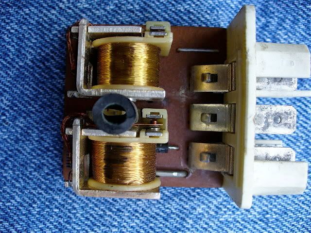
The Fuel Injection relay is actually two (2) relays in one:
a) The "System" relay is energized when key is turned on, and sends +12V out on the blue-yellow wire (87/1) to prepare the FI system for running.
b) The "Fuel" relay gets +12V to its coil (85) from Main relay 87/1. Coil ground (86/2) is controlled by ECU (pin 20) yellow-black wire (described in the sequence below the photo).
Photo shows FI relay with white cover off. System relay above, Fuel relay below. Note the piece of tubing holding Fuel relay armature closed for testing. Pumps should run as soon as the relay is put in its socket. Turn Key on to energize the System relay and motor should start when cranked, if ignition is OK.
FI Relay, Fuel relay forced closed
Start-Run Sequence
1) During starter cranking, the Crank Position Sensor sends timing pulses to Ignition Control Unit (ICU)
2-a) The ICU propagates these timing pulses to the Power Stage (aka Ignition Amplifier) to initiate spark at the coil.
2-b) At the same time, the ICU also propagates these timing pulses to the FI ECU, to allow FI operation
(no ICU pulses means no FI operation).
3-a) The FI System) relay (previously energized at Key On) powers the AMM, IAC, ECU, RS relay/Injectors, and Fuel (pump) relay coil + side.
3-b) When ICU pulses (2b) are received by the FI ECU, it "energizes" the Fuel relay (completes the relay coil ground side) to run the fuel pumps.
When this sequence is successful, the motor starts and runs until the Ignition is switched off, which in turn shuts down the FI system.
============>
Please explain: "First the fuel pump relay base is incorrectly marked"
How so?
And what does "caos" mean?
--
Bruce Young, '93 940-NA (current), 240s (one V8), 140s, 122s, since '63.
|