|
Well, I had this worn tranny/gearbox cover that was of no use to me so, what the hell, I decided to do some experiments.
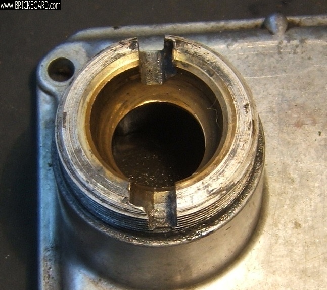
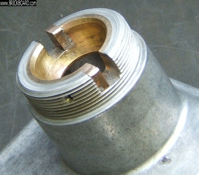
To recap, this is what the slots looked like before I started (pic 1):
First, I heated the threaded boss region of the cover (using a butane/propane torch) to a temperature at which solder would melt, and ascertained that this did not buckle the cover, let alone melt the die-cast part of it. Also no sign of the heat causing separation of the brass insert from the die-cast part. So far so good.
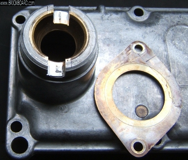
I found some 4 mm brass plate. I then cut away 4 mm of the worn flank of each of the slots (the clockwise flank - the other flank showed virtually no sign of wear). In other words, I widened and squared each slot, but on one side only. I used an ordinary hacksaw blade for this. See pic 2, which shows the widened slots and the brass plate – no prizes for recognizing where this came from:
I cut two repair pieces from the brass plate. I then held each of the repair pieces in position and drilled a hole from the side through the threaded boss and the repair piece, to receive a 2 mm diameter brazing rod. See pic 3:
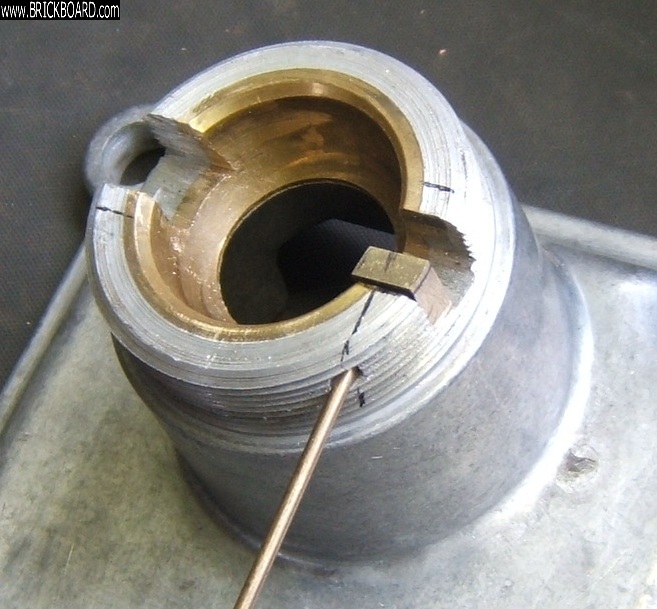
I then filed the repair pieces roughly into shape and cut two locating pins from the brazing rod. See pic 3a:
I then tinned the various surfaces that are to be joined (including those between the repair pieces and the locating pins). This is important because otherwise it is difficult to form a proper soldered joint. I then held the repair pieces tightly in place by pushing a few small steel plates into those parts of the slots not occupied by the repair pieces, and knocked the locating pins into place.
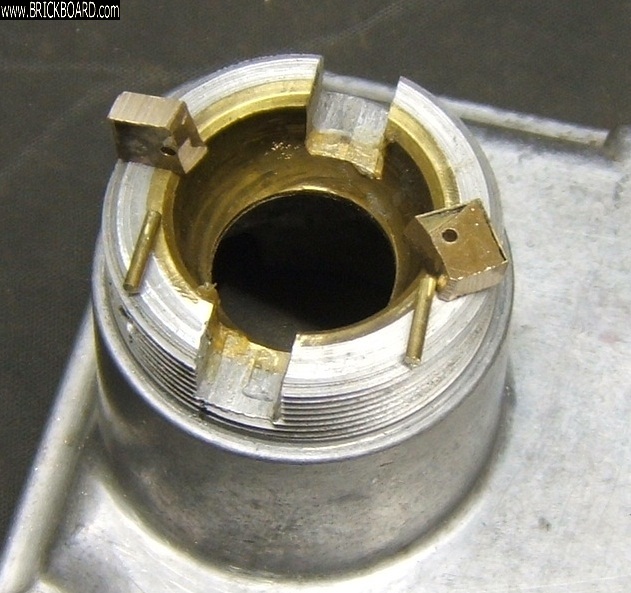
I then heated up the whole lot again and, when the right temperature was reached, flowed solder into the joints. After everything had cooled down again I tidied up with a file, removing excess solder and protruding parts of the repair pieces. See pic 4:
I am very happy with the end result. I must add, of course, that I haven’t tried the cover out in practice, but it looks pretty solid to me. The majority of the forces during use act in a direction perpendicular to the flanks of the slot and are not borne by the solder or locating pins. The solder and locating pins will, I believe, have more than adequate strength to bear any forces that might be acting in a direction parallel to the flanks of the slots.
My only problem: I don’t need the cover, but at least I now have a good spare. Moreover, the procedure has been an interesting exercise for me.
Incidentally, I have discovered another part of the cover that is subject to wear: One of the steel pins on the underside of the cover. See pic 5 (the flat indicated by the red arrow):
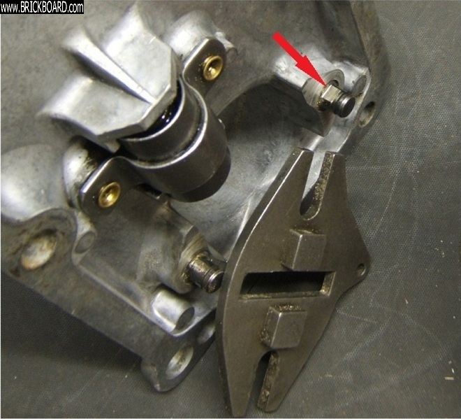
The cause of all this wear (the slots and the steel pin) seems to be the VERY strong spring force that has to be overcome when selecting reverse. One wonders why Volvo made this spring so strong, if the only purpose is to avoid accidentally selecting reverse when you want to select 1st. Or is there another reason for the strong spring?
|