|
Joe, I'll be quoting from a trouble-shooting manual that's not too well-written, and I can't actually see the items mentioned. But at least it may point you to something (I'll comment in parenthises on some points):
A - Right hood hinge area, "Power supply (to ICU) and IGN Signal (?). These are critical." connectors."
(Implies 2 connectors. One should have a Blue wire�from "hot" side of Fuse 11 to ICU pin 2.
The "IGN Signal" may mean a "pigtail" of the same blue wire. My diagram shows it going to the large Ballast resistor in that area. But if it's not even firing when cranking, this Blue wire circuit is probably not at fault, because the Coil gets power straight from the starter when cranking (Brown wire).
B - "Dist. 3 - wire Connector should have sleeves. C - ICU Connector...clean, tight pins."
D - "Conn. for Coil Terminal 1." (Right Front leading from ICU. White or Gray coil negative wire.)
E - "Worn thru wires under Engine by crank."
F - "Worn thru insulation, White (or Gray) lead to Coil terminal #1." (at or near coil)
G - "Micro switch." (CIS sw. on T. Body, Orange wire to ICU #7
H - "Fuse Box" (Power on Blue wire, unfused hot side input to fuse #11. From Ign. Sw., Key ON)
J - "System Ground, Intake Manifold, Red Sleeve on Black wire." (On "throttle machanism" bracket.
There are also "live" tests for both Hall Sensor (tests circuit to ICU) and ICU (force a spark with jumper). Let me know if you want them.
--
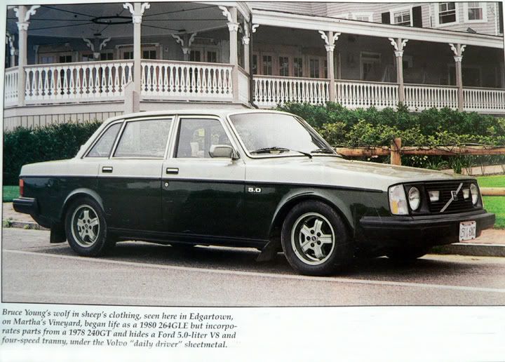
Bruce Young,
'93 940-NA (current)
'80 GLE V8 (Now gone)
'83 Turbo 245
'73 142 (98K)
'71 144 (track modified--and still here)
New 144 from '67 to '78
Used '62 122 from '63 to '67
|