|
Hello,
I will now post photographs to expedite my successful conveyance of the proper and right solution. If you discount my ability to read the factory diagram, I can electronically transmit it to you, so that you may use your own deduction.
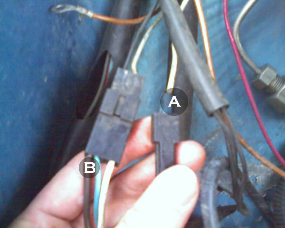
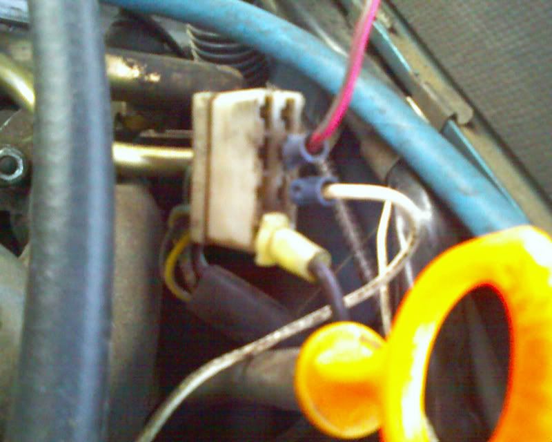
The first item of note is the firewall connector, second, Ignition control unit connection, and third, ignition coil.. You can see that the electricity flows to the computer first (A), and to the coil next, except while starting.
I used my original 1977 264 ignition ballast resistors, in order to improve the quality of useful life for the electronics. On some diagrams it is included, and on others it is not for the 1984 Volvo LH-Jetronic.
Lucid, it is quite moot to argue that electricity does not flow, I was referring to wire routing.
I have found many faults that existed because of old switches, and so I utilized relays as effective solutions for the horn and ignition ON conversion electrics. Now I can build an effective alarm system.
There are many details and an oration is not in order. I hope you will find I am quite ready and able to help you proceed in a logical fashion and establish total operation.
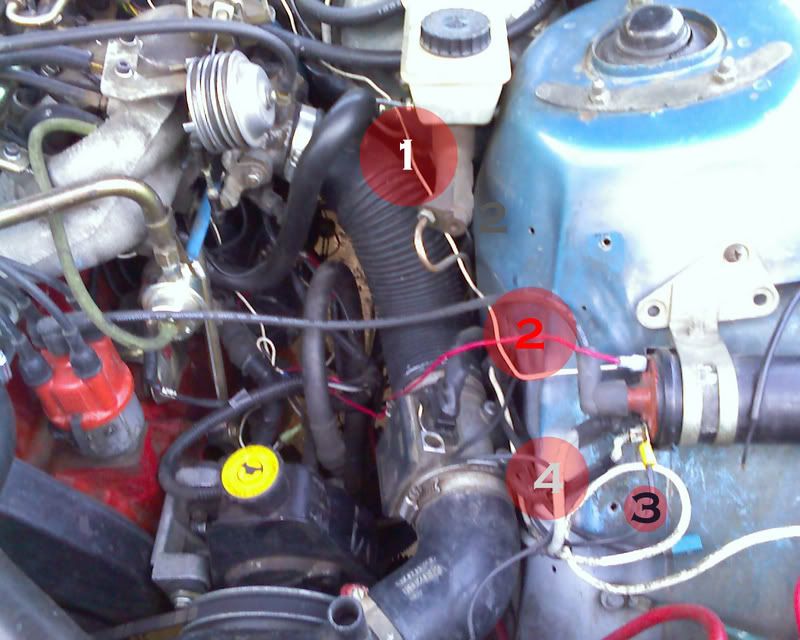
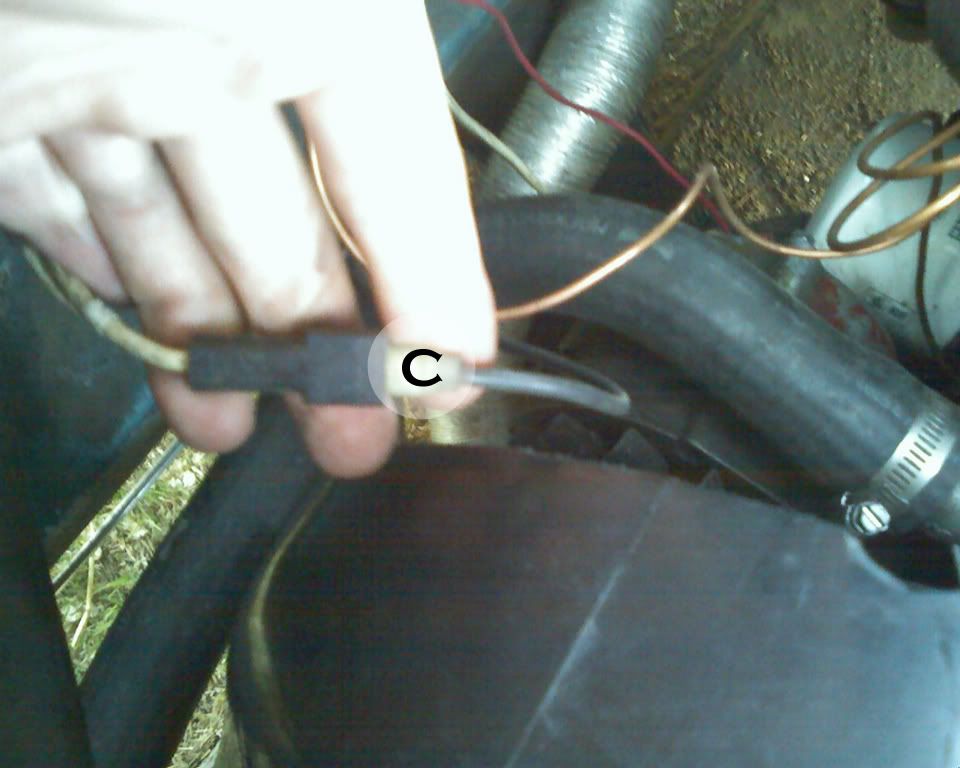
In the photo above and below there are four wires marked, they will be:
#1 : Ignition computer to positive on ignition coil
#2: Starter motor connection
#3: Grounding Strap of ignition computer
#4 Fuel Computer signal wire
A: Ignition computer power
B: Ignition coil positive
C: Grounding Strap of Ignition computer
There are serveral connection that I've not connected as you see, the only one needed for my operation is the starter solinoid #5 on the grey firewall junction, as I have ran another connection to the ignition relay. You need connection #7 on your vehicle for this purpose.
Goatman
|