
|
|
1992 245 B200F M47
LH2.4 Jetronic
Problem: engine idles steadily and at the correct 750 rpm after every start, cold or warm, but usually shoots up to 950 rpm after use of the car. This is intermittent, but it usually idles at a steady 950 rpm. It usually occurs directly after driving off or may take some time. Engine temperature seems to have little or no influence.
Also when coasting, it idles at 1200 rpm dropping slowly to 1000 rpm and only drops down to 950 rpm after coming to a standstill.
At the moments when it does idle correctly, coasting results in a sharp drop to 750 rpm one or two seconds after releasing the gas pedal, coming to a standstill does not affect idle any further. Some people say it should coast at 1000 rpm only to drop to 750 rpm when coming to a standstill.
The usual suspects have been eliminated:
- new IAC,
- TPS functions reliably and is adjusted correctly
- TB cleaned and functioning correctly
- no vacuum leaks
- ECT within spec
- AMM not faulty
- VSS present
- no fault codes
- electrical connections cleaned
- ground connections on intake manifold and between head and firewall cleaned
- pcbs of both ECU and EZK inspected and through hole components resoldered
- electrical signals measured at ECU and EZK, all present and correct, apart from when engine idles high, then signal to IAC is set differently.
Basically it looks like the ECU/EZK decides - for whatever reason - to idle the engine 200 rpm higher most of the time.
I am running out of ideas and these particular symptoms don't show up in threads or FAQs.
Any suggestions what I might check next?
Your help is much appreciated.
|
|
|
|
|
Time to revisit my thread.
I have found a kind of workaround. If I apply enough throttle when the engine is cold and while manoeuvring, then the high idle state is unlikely to occur. However, if I rely on the IAC to keep revs constant while manoeuvring on a cold engine (meaning I only apply the clutch and let the IAC do the rest), then the high idle state is likely to occur, regardless of the engine temperature, and can be sort of reset by shortly turning off the ignition.
I don't know why it works this way, but it does.
|
|
|
|
|
This may be completely irrelevant, but I'll post it for information.
My 1991 940, B200F with LH 2.4 and M47 also idles high after I have run the car over 60mph. The reason appears to be that I no longer have the speedometer signal going into the system. I had to replace the Yazaki Speedo due to the well known issues with the capacitors. The car idles perfectly at around 750 rpm until I take it over that speed, then it idles at circa 1100rpm. To correct this I simply have to switch off and switch on again. This restores the correct idle. I can't understand the logic of why the ECU should be set up like this, but presumably Volvo did this deliberately. Prior to my removing the speedometer signal of course it worked as it should, idle returning to normal after a fast run.
Ian F
|
|

|
|
Hi Ian,
Your response was my knee-jerk thought when I read the post from the OP, "Grey245" but reading it a second time I see he does not note the 311 code and specifically says the VSS is present. Yes, this function you've lost, Ian, is deliberate and about the only way the Bosch engineers could conceive of to know whether your car was warming up in your driveway, or driven down the highway.
But OP's claim to have a B200 using LH2.4 in '92 with an M47, and her choice today of nicknames might lead one to believe the car is gray (or in British English grey) market here in US or standard fare in another market. I haven't any clue what to make of it.
--
Art Benstein near Baltimore
Nobody sees a flower - really - it is so small it takes time - we haven't time - and to see takes time, like to have a friend takes time. - Georgia O'Keeffe
|
|
|
|
|
I am indeed located in the 'old world', though not the UK. A long time ago I used to be on this forum as "Grey245Polar" but that account seems to have been suspended. Grey refers to the colour of the car, not a grey market.
The 1986 cc B200F is a smaller bore version of the 2316 cc B230F sold in some markets. It is only 5 BHP down on power, but must make do with quite a bit less torque.
I am at a loss, but I have not yet given up.
Now I know that the ECU is supposed to "learn" for the first 10 miles or so after a reset or disconnection of the battery. But I can't really say that I ever noticed anything different.
To those who do notice it, what are the differences in driving experience in those first miles? Does the idle run higher after a reset?
|
|
|
|
|
Oh, I remember the polar part of your login name despite my general ignorance of the European market for Volvos. Seems I read somewhere that 2000cc was a taxing cutoff for engine displacement having a large impact.
Yes, the LH2.4 ECU does an instant reset of learned trim when the power is removed but to characterize the difference between the baseline and the trim learned depends on the individual car. For example, the trim adjustment makes up for intake leaks, throttle plate wear, cylinder wear, long term fuel pressure changes, and compression changes due to soot buildup. The combination would be different individually. I've noticed in one example, after a reset, the engine stalled before I got out of the driveway.
Idle speed shouldn't vary at all, I think, given a properly operating TPS (here in the States you'd probably have LH3.1 with an M47 in '92), a correctly adjusted throttle plate stop, a clean idle air valve, and of course, the VSS present. And there's nothing I know about the trim adjustment the ECU makes after a reset that would purposely set the idle higher.
I could guess that a throttle plate stop adjustment problem could lead to enough extra air that the idle valve's correction ability would be out of range, and that could show up after the motor was warm. Turning the key off and restarting would not change that condition, like it does with a missing VSS. And you've already discounted any dependence on warm up or temperature.
If I read your post carefully, especially the part about the signal to your new IAC being different during the malfunction, I'd be inclined to suggest you try to find another fuel ECU to try. You seem to have done your homework. Curious about this; which one is it? I'm only familiar with -933, -951, -561 versions of LH2.4. Maybe one designed for the B200F has a different way to deal with changes to idle speed. Assuming the signal change you see toward the IAC is increased duty cycle, by how much?
--
Art Benstein near Baltimore
"Politics is the systematic organization of hatreds." -Henry Adams
|
|
|
|
|
Hi Art,
The "smallish" B200 engine was indeed used for tax reasons (e.g. Italy has a cc based taxing system) or to be able to offer a cheaper entry level engine in some more frugal markets. It was also used in some smaller Volvos, like the 300 series, which never made it to the US. In those it was the larger option, the smaller capacities being engines acquired from Renault.
My 245 was registered in January 1992, so it might actually be a 1991 model.
I measured on the EZK and fuel ECU pins according to https://ipdown.net/jetronic.info/tiki-index.php?page=LH2.4+Pinouts+and+Diagrams, noting that my 245 has no EGR or airconditioning.
I also measured a lot as described in https://vdocuments.mx/lh24-manual-complete.html (TP31361/1).
I don't have a DMM that can measure the duty cycle, however I read a different DC voltage level when it idles high. When it idles at 750 rpm, the voltage is 8.5 VDC and when it idles at 950 rpm, that voltage is 8.2 VDC.
The fuel ECU is a white label -561. And yes, by now I realize I need to find a functional replacement.
Thanks for your help!
|
|
|
|
|
Extremely interesting technical discussion here related to your idle problem -our experts are seemingly fully engaged for you. Thanks for posting those links with the LH 2.4 Jetronic Volvo Service Manual and Pinout/Connector Diagrams -pure gold.
As for your thoughts on swapping out your -561 ECU, here's a few compatibility tips that may help with sourcing.
I note from Bill Garland's ECU page (showing primarily North American market applications) that the LH 2.4 -561 ECU was used on the B230F in the 240 (1989-1992?, with 1992 more likely to be LH 3.1) and 740 (1989-1990). The original pink label ones were known to be problematic (most notably the fuel pump control circuit could fry, a no start condition, also affected the pink label -562 used in the B234F). The revised white label one that you have is known to be more reliable, but my recollection of user reports is that it's still not as reliable as other variants.
The -933, -935 and -951 are listed as good substitutes, but I'm wondering if you need to be careful about EGR vs. non-EGR (yours). Bill's tables suggest it may not be an issue for you and that makes sense as EGR is mostly on the EZK side. If there is an EGR pin on the ECU (I haven't looked) then to make an EGR ECU work without EGR you might need to so something like ground or sever the cable pin.
The difference between variants can be as little as the PROM, so opening them up and doing a PROM swap is an option to consider if you get stuck sourcing a suitable replacement.
On your raised idle problem in general, my first thought and I'm sure that of many was the ECT, but your diagnosis suggests that's out of the equation. Another thought is always the A/C being engaged, but you say you don't have that. Rather grasping at straws here and your diagnosis appears to be beyond this, but I'll mention them anyway as these are common idle problem areas. While idling too high or too low, don't forget to give the IAC a few good taps to make sure it's not sticky. I did like thoughts about the throttle plate and the TPS not being adjusted correctly, so do double check that the TB throat is clean, check the stop screw adjustment (using the 1/4 turn method) and make sure the TPS isn't set on the hairy edge of triggering, plus make sure the TPS is in good working order, with your DVM seeing a fairly crisp and solid cutover to indicate the contacts are in good shape.
Oh, and to most of us here in Canada and also Australia/NZ, probably SA as well, it is colour me grey, not color me gray, so that was not overly revealing of your locale or heritage, but the 2.0 litre thing does rather suggest your continent. Be on the lookout for one of those rare 16-valve 2.0 litre 700s (possibly an early 900?) that found their way into the Italian and Belgian markets in the late '80's (and early '90s?). Reportedly, the B204F (forerunner of the B234F) produced something like 170 HP, while the B204FT produced something like 190 HP, pretty impressive by brick standards (there was no B234FT). I thought that was an ingenious way for Volvo to deal with the 2.0 litre taxation issue using existing engineering (in conjunction with SAAB?) and production capability.
--
Dave -still with 940's, prev 740/240/140/120 You'd think I'd have learned by now
|
|
|
|
|
Thanks for your elaborate answer and the compatibility list.
That list indeed lacks the B200 application.
Previous to my current 245, I had had another one for about 12 years. That car was identical to the one I have now in every respect. It was also registered in January 1992 and a look at the VINs of both shows they are only 918 apart.
I found some photos I took of the ECU of that previous 245. Surprise: it had the -936 ECU, and although the label of the EZK isn't fully visible, I can just make out it must be different too. The current one being a 0 227 400 176 and that one a 0 227 2?? ????.
Hmmm...I wouldn't be surprised if a previous owner swapped in a ECU/EZK combo from a different car. The connectors of both show signs of measurements taken the wrong way and when I had just bought my current 245 I found a wire had been added to make both fuel pumps run continuously as soon as the ignition was switched on. I also found two spare main relays.
Today I went for a hike at about a 45 mins drive away from home. I took the opportunity to measure some of the signals going to/from the ECU and EZK while on the move, stopping a few times to change the measuring leads.
Everthing looked fine, but I found that "IAC" is a misnomer. That valve is adjusted all the time, not just when idling.
I experimented a little and found that it adjusts the IAC according to certain conditions.
At cruising speeds and part throttle, I measured voltages of around 7.6 V. Only the speed seemed to affect it.
Idling at a standstill sees something like 8.6 V and when you engage the clutch without touching the throttle that voltage drops to compensate for the load dropping the engine rpm. The IAC is turned open to allow more air into the engine. So far so good.
Then there's slowing down with the clutch engaged, the voltage slowly rises as the speed drops. But when I then depress the clutch, it quickly rises to a normal idle voltage, vehicle speed being no longer a variable to be considered.
So the ECU must be able to ascertain whether the clutch is engaged or not, does it determine that from the AMM?
At moments when the engine idles high, depressing the clutch and coasting does not see the sharp drop, but a gradual one and a last one when VSS shows the vehicle has stopped. It's as if the ECU thinks your engine braking rather than coasting.
The other function of the IAC is to control the intake vacuum, hence it's always adjusted by the ECU. I knew that but I didn't expect it to be adjusted while cruising.
I'm still unsure as to what's going on. But while testing the knocking sensor by almost stalling the engine (foot on brake and slowly engage clutch until it almost stalls then depress it quickly) I found that often the idle returns to 1000 or even 1200 rpm.
These are nice round numbers, so it seems more and more to me that the ECU performs a deliberate function, for the wrong reason.
Sorry if this is getting a bit messy and complicated.
|
|
|
|
|
These are ECUs list including for B200F engines:
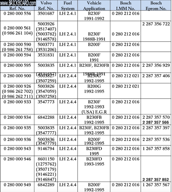
In order to tell which ECU is for manual transmission, you'll have to cross reference ECU number with UK or Netherlands used car website, where B200F is widely used.
Hope this helps,
Amarin
|
|
|
|
|
Your list says the -949 ECU should have the 1 267 357 567 Eprom.
Today I opened my -949 again and found a 2 287 357 567 Eprom in it.
It's probably no coincidence that the last six digits are the same. But why the first four are different, I don't know. It looked like I was the first to open the housing of the ECU since its manufacture.
|
|
|
|
|
"Your list says the -949 ECU should have the 1 267 357 567 Eprom. Today I opened my -949 again and found a 2 287 357 567 Eprom in it"
So this must be some other variations of your -949 ECU but not listed within the last column ie Eprom number. Unfortunately the list is not exhaustive. I have two -935 ECU with same Bosch and Volvo number but with different Eproms inside. The thing is one was made in Germany (2 287 357 397 Eprom) while the other in Spain (2 287 357 568 Eprom). Different setting resistors too - Germany uses 3 while Spain uses 2. Both works well but the one that came with the car (Spain) performs a little bit better (maybe because I've replaced the caps).
My guess these would be for different markets, fuel octane, model variations (sedan/wagon), accessories (AC/no AC) and emissions requirement.
Regards,
Amarin
|
|
|
|
|
My guess is that these ECUs would have been a bit more universal than that.
Different markets would have gotten different part nos. How else would you distinguish between them in a warehouse when they all carry the same Bosch and Volvo part nos?
My non-aircon, non-EGR, manual has all those pins present in the wiring loom, but the relevant signals will only mean anything when they're pulled to battery voltage, e.g. by switching on the airconditioning. In my model these are simply tied to ground.
IMHO, these ECUs all started out identical, but the setting resistors and Eprom determined the application (and with it the ECU part nos). In the analog domain signals from the sensors might be different between capacities (e.g. AMM) and hence need slightly different limits (that LM2903 is a voltage comparator).
At the same rpm a B230 will draw in more air than a B200, so the AMM will give a different signal. The Eprom contains the tables for the specific application, B200, B230, turbo, etc, that the manufacturer compiled during engine characterisation and testing.
Over time it's not uncommon to see a design get simplified to save cost by reducing the component count. It will still do the same, but with fewer components. That may be the reason why those ECUs share the same part no but are different inside.
Just for fun I attached a photo of the white label -561 (left) and the -949 (right) side by side. Can you spot the differences?
The Eprom on the -561 did not have a label on it. The hybrid modules look identical.

|
|
|
|
|
"Over time it's not uncommon to see a design get simplified to save cost by reducing the component count. It will still do the same, but with fewer components. That may be the reason why those ECUs share the same part no but are different inside."
Yes, I expect the assembly part number to reflect changes to fit, form, or function making accurate inventory possible. And I think it does generally, with these Bosch ECUs, but I felt they stretched the "function" rule just a bit when the hybrid's reliability was improved with the only indication in inventory being the color of the label.
Thanks for trying the TIP-122 as an injector driver replacement and doing a great job of documenting it. It hasn't happened to me yet, but I've seen several posts describing symptoms of a shorted injector driver. Mostly, I think, after trying in a turbo with different injectors.
--
Art Benstein near Baltimore
“Never underestimate the difficulty of changing false beliefs by facts.” --- Henry Rosovsky
|
|
|
|
|
Thanks for the list!
At least this confirms that the -561 is not meant to be used on a B200F and that the -936 (which is) has a different Eprom. I have a -949 coming my way, I hope it's any good, but it only set me back € 32.50 including shipping, so I was willing to take the risk.
|
|
|
|
|
Bump.
I just want to keep this thread alive, because you bring up some very interesting questions. For instance, whether the car knows anything about the clutch. I'd be surprised by that. Also, that your ECU was probably changed, and at the least, investigated by someone leaving traces.
Another thing has me chagrined. One year ago this month I took some readings in an attempt to correlate the amount of air passed by the IAC as gauged by percentage of full open with the duty cycle. In doing so, I also noted its behavior with and without closure of the TPS contact, doing so by electrical breakout and not by moving the throttle. I can't find my notes. Just uncaptioned scope traces and pics of IAC valves.
Worth doing again, I think, but presently I have only -951s to play with, which I believe do the injector cutoff on decel, and the measurements I took were in the driveway, perhaps not those you'd get after VSS told it actual driving was being undertaken. Also, the cars I have with LH2.4 are automatics.
By posting this, I will surely find my notes tomorrow, right? That's how it usually goes. In any event, I hope you come back and keep this thread going.
--
Art Benstein near Baltimore
The older I get the faster I was.
|
|
|
|
|
It has been a week since my last post. Other than contacting a seller who has a -949 ECU for sale (supposedly from a B200F 940), I have done nothing about the problem. It's actually more of a nuiscance than a problem because all other aspects of driving seem fine.
I have done some more thinking, and my problem seems to point towards the engine load as measured by the AMM. Mainly because all the other signals measure fine.
The AMM signal does measure fine, though, but I'm not sure if the "wrong" ECU for the engine will lead to the desired result. Surely the smaller displacement results in a smaller airflow through it?
The IAC signal clearly rises suddenly when the clutch is disengaged during deceleration.
The ECU must know whether the car is engine braking or coasting, otherwise it would be impossible to regulate intake manifold pressure and with it crankcase ventilation.
At first I thought maybe the fixed ratio between engine rpm and VSS when the clutch is engaged is used to determine that, but quickly discarded that idea.
This is what I think now:
During engine braking the car's momentum has an effect on the engine load. It cannot idle freely. Lift that load by disengaging the clutch and it can.
Since there's no clutch position sensor, that only leaves the AMM and engine rpm signals to derive it from. Depressing the clutch results in a change of both.
As an aside: while searching for LH2.4 Jetronic info I found that it's not a widespread system. Mainly only found on Volvos, Saabs and Porsches.
I also stumbled on this site (https://home.kpn.nl/mirjam_paul/928_lh_repair.html) of someone repairing faulty LH2.4 ECUs from Porsche 928s. Seems that the hybrid module is a common cause of problems.
To be continued.
|
|
|
|
|
While looking at some old links, I stumbled on our 2017 conversation about tank sender feedthrough failure analysis.
My trip to town is about three miles (5 km) and descends roughly 500 feet (150 m). When I dare drop the AW70 into neutral going down the hill, foot off of the accelerator, the large tach looks to be showing normal idle rpm as best as the resolution between 0 and 1K is on the gauge. The difference I think I notice since replacing the -561 with the -951 happens when it is in gear (as much as an auto is in gear decelerating) with the engine rpm dropping further than I recall it doing with the -561 which was native to our two '89 240s. That's my only evidence for believing the later ECU cuts the injectors based on VSS and TPS inputs at above-idle rpm. I hadn't considered load derived from the AMM.
That Porsche hybrid replacement is the second version of aftermarket I've seen. The first, I believe, was built with discrete surface mount parts by one of the ECU repair outfits here in the US. It impressed me that there could be a market to repay the R&D needed to reverse engineer and design a substitute for Bosch's hybrid on ceramic. The photo of bum hybrids collected is explanation enough!
One of our Brickboard users made a few dollars many years ago cruising the yards for -951s and white label -561s sending them to Europe, I believe. Mike was interested then in distinguishing the two versions of that hybrid microcircuit to verify the fix was in the white label (yet identical part number) ECUs.
The hybrid is the obvious difference between the pink label 5xx series and those with a white label. Of the 7 symptoms given for hybrid failure, the most common, and the one I've experienced, is #4, loss of fuel pump relay ground. Interesting it is, to note #6 in the list: RPM regulation at idle. Some of the same info was posted here about 17 years ago.
As Dave Stevens notes, the 5xx series enjoys a poor reputation, although my reading has not encountered any reliable anecdotes from the community citing specific problems with the white label units having the improved hybrid.
The idle symptom might be a nuisance, but more than that, its a brain teaser, much like the tank sender epoxy failures. Might take you some time, but you'll figure it out.
--
Art Benstein near Baltimore
If there is a book you've wanted to read but nobody has written it yet, you are the one to write it. -Tony Morrison
|
|
|
|
|
Thanks for those links, I read through some of them. This passage might explain what's going on with my idle problem:
"To understand the function of the hybrid, please envision it as a type of interface that converts the 5 Volt signals of the microprocessor to 12 Volts, or 12 Volt signals of the controller to the level lower 5 Volts for the microprocessor. Additional functions such as Lambda regulation, resets and reference voltages are also integrated."
All this time I have the suspiscion that the ECU goes into some sort of state it will not recover from, at least part of the time. That bit about resets and reference voltages seems to point towards that. The fact that I may have the wrong ECU for the engine may worsen the problem.
I have purchased the -949 ECU and I am awaiting delivery.
|
|
|
|
|
I note from the links provided by both you and Art on LH failure and repair the following symptom is listed
o Automatic Transmission: no RPM regulation (idle speed) when switching from "D" to "N" or "P".
So it seems you’re on the right track as that very much agrees with your clutch load/noload observations, although there’s no explanation of why that happens.
Like you say, the ECU can only see (deduce) the clutch pedal, brake pedal and shifter indirectly through the CPS rpm and AMM air flow and maybe the TPS to suggest your foot is also off the gas pedal or the speed sensor to suggest you’re at a standstill.
Maybe on the board under certain operating conditions some failing circuit is leaking out into the ECT circuit nearby, which would directly affect base idle. At this stage for you, I’d want to try opening up the ECU, inspecting for hot spots, cold major solder joints, cleaning the solder side (like with a toothbrush and circuit board cleaner or 99% isopropanol), using compressed air on the component side, maybe even flushing the component side (like with spray circuit board cleaner, contact cleaner or non-residue spray AMM cleaner).
As for the evidence you saw of a PO having replaced the ECU in your 245, although I would expect the pink label -561s were out of the supply chain by 1992, it would make you suspect it was originally a pink -561 with someone having previously bypassed the failed fuel pump control circuitry (which the pink label ones were infamous for) as a temporary fix until they could find a white label one.
--
Dave -still with 940's, prev 740/240/140/120 You'd think I'd have learned by now
|
|
|
|
|
No, that's indeed not an explanation as that wire is permanently tied to ground in my manual car. Same goes for the airconditioning inputs as my car doesn't have one.
At speed, I seem to remember that - while decelerating - only the speed and clutch had an effect on how the IAC was controlled.
The pinout diagram mentions the information of a closed TPS is either used to start a special idling program or is relevant during fuel shut off, so at standstill/low speed or during engine braking.
I had already inspected the insides of the ECU and EZK. On the ECU I cleaned the board around the opamp as it had some white residue, presumably flux residue. The rest of the board looked absolutely immaculate. I was impressed by the solder quality (and I was in that industry for nearly 19 years, so I recognize a good solder joint when I see one). Despite all this, I resoldered every through hole component just to exclude the possibility of a microscopically cracked joint.
The only part I replaced was the main 470uF/40V electrolytic as its ESR measured a bit high (to be expected at its age).
I don't think my car should have the ECU of the B230F, but it does. Now I have one of a B200F coming my way, and I wonder if this has any other effect than hopefully curing the idling speed issue. To be continued.
|
|
|
|
|
Volvo 940 2.0 0280000949 LH2-44
I found a couple of these on line, never seen one in the US and never seen the LH2-44 designation. You may be on to something!
Dan
|
|
|
|
|
Today I received the -949 ECU and after a quick internal inspection to see if there were no tell tale signs of blown components I tried it on my B200F.
Turning the ignition on led to the normal sound of priming fuel pumps and the clicking of the relay. Sadly I can't start the engine on this ECU. The starter motor cranks fine but it won't start. Soon there was the smell of unburnt fuel.
I then hooked the -561 back up and couldn't start the engine on that one either. Oh boy, did I brick something? At least the fuel pumps seemed to work and there was a spark.
Then when I had waited a little I tried again and the engine spluttered back to life on the -561 ECU and ran fine once the excess fuel was cleared out.
Just to make sure I tried the -949 one more time with the exact same result. Again no start and again I took some time to get the engine going on the -561. As if the engine had been flooded.
So, either I have a dud -949 or it it isn't compatible with the 245. According to the list Amarin posted in this thread both the -561 and the -949 are used with the same AMM. But that has me wondering...what about the EZK? Does that not also need to be swapped out for a different ECU/engine?
|
|
|
|
|
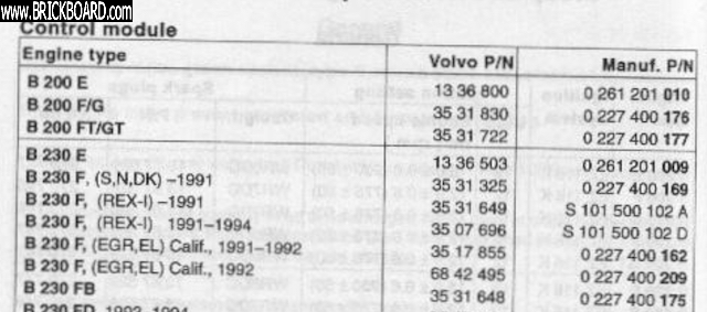
Yes the EZK module should be paired with its respective LH module. There's only one EZK listed for B200F. Check if your current EZK tally with the ones for LH module B230F up to year 1991.
Amarin.
|
|
|
|
|
Thank you again for a helpful list.
However, my current setup of a -561 ECU (B230F) works fine on a -176 EZK (B200F).
What I negleceted to do yesterday was read error codes from the -949 ECU that doesn't work. So this morning I swapped the ECUs again. Again a no start condition, but also no error codes.
Then I tried the so called "control function 3" that alternately operates the injectors and IAC for a couple of times.
Aha! There were no clicks from the injectors, the IAC did operate.
So that's where the problem is coming from. In other words my flooded engine "diagnosis" could not have been right unless the injectors were kept open all the time (hence the smell of fuel and hence the temporary trouble starting on the functional ECU afterwards).
Sadly I seem to have a dud -949 but I have found someone dismantling a B200F 245 that I am in contact with. Lets see what he's got.
To be continued.
|
|
|
|
|
Problem solved!
I contacted the guy with the ECU and EZK combo on a 245, but he wasn't willing to part with them. Originally he had intended to strip the 245 and sell off the parts but now had reconsidered and decided to sell it on in working order.
So, I had another look at the pinout diagram and noticed that pin 18 is pulled to ground when the injectors are supposed to work. The symptoms with my dud -949 seemed to point to a burnt through driver transistor as they were continually pulled to ground. Some tracing later and sure enough, T402 measured quite low resistance between C and E. Here's where my 19 years in the electronics industry was usueful.
That transistor was an ON823. Never heard of it, couldn't find much info other than that the bog standard TIP-122 Darlington transistor is a suitable replacement.
The only shop in town left selling electronics components had them in stock, so an hour later I was back home and replacing the defective T402.
When all was finished I connected the bare board temporarily on the connector in the footwell and tried control function 3 again. SUCCESS! The injectors clicked!
And of course now the engine would start just fine.
I decided to replace the main 470uF/40V capacitor as well just as a preventive measure as these things usually don't age all that well, losing the electrolyte and with it capacity over time.
While I was at it, I opened the -561 up again for a side by side comparision.
The designs are not identical, suggesting that the -949 is a newer one.
Date codes on the components suggest that these boards were manufactured not at all long apart, perhaps even in the same quarter.
In one corner of the board there are standoffs on which some setting resistors are placed. I'm guessing these are meant to set some limits for comparators in the analog domain. And sure enough, the -949 had different ones in there.
I made some photos of both ECUs, so if anyone is interested, let me know and I'll start another thread.
But the proof of the pudding is in the eating, so I went for a test drive.
I'm pretty sure the replacement of the ECU cured the problem. Not only does it drop back to 750 rpm idle all the time, acceleration when cold feels a little more fluid, less "wobbly" than on the wrong ECU. Other than that, the driving experience is pretty much the same as I was used to.
That transistor on the left in this borrowed picture (http://forums.turbobricks.com/showthread.php?t=227153&page=55) was the culprit of the non functioning injectors.
It is the driver for the injectors and was fried. A new one (the TIP-122) in its place was all that was needed to resurrect this ECU.
As for why the -561 doesn't work too well in my car, I'm not sure. It could be incompatibility or it could be that it's starting to fail. Who can tell?

|
|
|
|
|
Good to hear that! You got your idle back!
The ON823 Darlington, made by Philips is unobtanium nowadays. It could only withstand 80V collector-emitter voltage (safety headroom for injector voltage back-spike). Bosch used this in my spare -934 ECU. In the -935 ECU that I'm currently using the component had been updated to BDX53C. This Darlington could withstand up to 100V (same for TIP122). Good news its still available at most online parts store. Bog standard caps with prescribed value is good enough for replacement. Using low ESR caps might get the LDO regulator into oscillation. And take care in desoldering the caps (transistors too) as the old copper traces might delaminate with undue heat.
Regards,
Amarin.
|
|
|
|
|
Thanks for the info.
I used regular BC/Vishay caps I had lying around. Industrial quality (formerly Philips), but non low-ESR.
The board is a good quality one. I had no delaminating issues whatsoever, twice as I had replaced the cap in the -561 too. The lead containing solder helps too.
However, the PCB of the -561 looked immaculate, the pcb of the -949 a little bit less so. Still good quality, but I could see some touching up had been done during manufacturing/QC.
|
|
|
|
|
Glad you figured it out. May I say this is one of the most interesting threads I've followed here in a long time, starting with a general symptom and ending with ECU variants and discussion of capacitors. Totally helped take my mind off all the sorrow and nonsense going on in the world these days. Thanks for posting and thanks for making this a two-way dialogue. I can't think of a better example in recent history of how these forums work so well for both problem solving and education, pushing some of the better ones here to think a little harder and learn more about the central brain of our old beasts in the process.
--
Dave -still with 940's, prev 740/240/140/120 You'd think I'd have learned by now
|
|
|
|
|
Maybe I was a little too quick with drawing conclusions.
Today I had a 30 mins drive somewhere and everything seemed fine. A couple of hours later on the way back the car would not coast at 750 rpm but did so at 1000 rpm. And sure enough, at the next traffic light it idled at 950 rpm. Just like it did on the other ECU.
Turning the ignition off and then restarting the engine restored the 750 rpm idle, and it didn't misbehave on the next trip.
So maybe the symptoms have alleviated somewhat on the correct ECU, the actual cause must still be there. Bummer...
|
|
|
|
|
Was it your thread where I read about some previously done work suspect in skills? Could it be possible someone stuffed a meter probe into the female parts of the ECU connector and effectively made your VSS as read by the computer intermittent? Sure, swapping computers could temporarily change the condition.
One of the TB contributors learned about something like this the hard way, and has ever since been a very vocal proponent of the "drag test" which he uses where he works as an auto tech. He's looking to evaluate contact force by using a male terminal identical to the one being tested to check the tension in the female.
The reason I jumped on this was your being able to "reset" it by using the key, which is identical to the missing VSS syndrome. I don't know how many cycles it would take to raise the 311 DTC.
--
Art Benstein near Baltimore
He who obtains has little. He who scatters has much. -Lao Tzu
|
|
|
|
|
Yes, I found evidence of that on one contact in the ECU connector and one in the EZK. The one on the ECU looks slightly bent, the one on the EZK is missing one of the four springs.
However, they were the knock enrichment signal from EZK to ECU, which measured fine, it did get from EZK to the ECU and the one on the ECU connector I forget, but was somewhere in the middle. Definitely not pin 34.
I measured VSS to be sure, but already knew it had to be present as coasting in the "high idle condition" would lead to a drop from 1000 to 950 rpm shortly (a second or so) after coming to a standstill.
I read on Turbobricks the following (https://forums.tbforums.com/showpost.php?p=2852595&postcount=23):
"If the engine speed (RPM) is above 2100 rpm, the load signal is in the part-load range and the control module does not receive a signal from the speedometer for 8 seconds a diagnostic trouble code (DTC) is stored."
A missing VSS seems to be associated to much higher idle revs than 950, more like 1700 rpm or so. I have yet to see a 3-1-1.
I am wondering: why 200 extra rpm? It's always that number...
|
|
|
|
|
Why 200 rpm more? I keep wondering.
I decided to google something like "950 rpm idle Volvo" and found a thread about an auto in D or N. OK, so the auto in gear drags the rpm down enough to compensate that beforehand. Same thing with the A/C.
But I have neither and I made sure that those pins on the ECU were tied to ground. Or at least I was kind of sure, so I went over it again using TP 31361/1.
Did I say that unused signals are tied to ground? Well, with manual transmissions pin 30 should be tied to ground. Confirmed that.
Now what about the A/C pins 14 and 15?
I don't have an A/C, so I assumed they would be tied to ground to simulate an A/C that's switched off. Unfortunately, TP31361/1 doesn't mention cars without A/C. Just that pin 14 should be about 0 Ohms to ground and pin 15 1kOhm to ground with the A/C switched off.
In my case there was infinitely high resistance between pin 14 and ground and 15 and ground.
I had already meaured voltages on these pins close to .2 V or so during driving, so I thought I had eliminated that as a possible cause. I assumed a pull down resistor internal to the ECU would take care of an unconnected A/C.
Now I have run a wire from pin 14 to ground to make sure that is pulled hard to ground at all times, simulating an A/C compressor in the off-state. A first test drive was successful, but I won't draw any conclusions just yet. Time will tell...
To be continued.
|
|
|
|
|
"Why 200 rpm more? I keep wondering."
Yes, good point. It sounds like an even number planned to keep the AC compressor's intermittent load from taxing the idle speed regulation loop. I don't recall if you found that number in the literature, but it does sound good. What I can't quite get a sense of, is whether you're seeing "200" as a couple needle-widths on the instrument cluster tach or measuring it with something giving you a few rpm's resolution.
Checking my notes on pin 14 and 15, I can't tell how the pin should look open circuit given the circuit is on the hybrid. But I did notice one unexplained difference between the 561 and a 933 I have to look at. The 933 has an unused pull-up resistor option (R215) which, on my example, looks to have been placed and then removed when the 9XX gets configured. The -933 is configured to mate with an EGR version of EZK.
I connected the 933 to power and saw only 150mV from either 14 or 15 open circuit, like you saw, so I doubt this is your fix, unless the harness on your car brings in some noise on those wires, which could be eliminated by your grounding them. Where do those wires go in a car with the standard climate control?


--
Art Benstein near Baltimore
The 50C5 was introduced in 1948, to address concerns that the set might pose more of a shock hazard to the user if the 35W4 and 50B5 were to be accidentally interchanged. The 50C5 is a 50B5 with a different pin-out.
|
|
|
|
|
Here's one from the -949 I had taken earlier.
Looks pretty much the same minus some circuitry, presumably for the EGR.
As you can see R215 has never been placed on this one. Can't help but notice that R315 got a little hot on your board.
Agreed, if the wires needed to be grounded on non-A/C cars, it would have been done in the factory. I tried to trace them, could see where they (14: GN and 15: GR-R) entered the wiring loom, but didn't see them exit. Logically, there would be a connector left hanging somewhere from the loom. I found several of those, but none with right colours.
Wether or not noise is the issue, I don't know yet.
But why are there TWO pins from the A/C to the ECU?
The difference between 750 and 950 rpm is pretty clear to me. Not just as seen on the tach, but also as heard by my ears. Even the drop from 1000 to 950 rpm can clearly be heard and seen, even if it's only a few needle widths on the (big) tach. I didn't measure exact numbers, but I have seen idle revs of 1000 and 1200 with the needle exactly on the respective marks. The 50 rpm drop is a guess.

|
|
|
|
|
"As you can see R215 has never been placed on this one."
Agreed. However, it appears neither R212 nor R213 made it into your 949. If the foil is the same on 9xx ECUs, your 949 has no use for the AC signals from pins 14 and 15 because they aren't connected to anything. If I'm right about that, you can end the AC-adjusted 200 rpm increase red herring.
"Can't help but notice that R315 got a little hot on your board."
Again, agreed. If the search function on this board searched everything, you could put "benstein R315" and find my analysis of this from almost 2 decades ago. Short explanation is R315 supplies the shift indicator open collector output to the bulb in the instrument panel behind an up-arrow icon. The same lamp is used for the manual transmission "time to upshift" reminder as with the automatic's OD disable indicator.
There's a violet wire from the ECU pin 26 called VXMAN that is supposed to be left out of the cabin harness connector to the fuel harness in cars equipped with AW70, but it got overlooked at the factory. The post is worth finding when others questioned the overheated resistor visually inspecting their computers, and in the occasional transmission-type swaps. With the violet wire jumper option incorrect the 1-watt resistor dissipates over ten times that amount when the auto transmission's solenoid is engaged to allow 4th gear.
I'm guessing quite a few ECUs used with automatics have a cooked R315, based on the few I've seen, and just how cooked depends on high-rpm driving habits.

If you agree the AC idle-up is not the issue in your car, you might have a look at pin 30. When I first traced this out I imagined it was used to adjust the fuel during cranking.
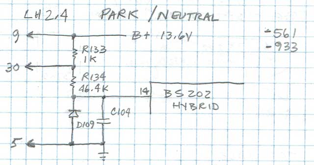
I'd dismissed the description "park/neutral" until realizing the connection it shares with the under-hood starter test socket is on the ignition switch side of the automatic's neutral safety switch, which in your car is a jumper wire. This came up while helping someone diagnose the voltage being read at the test socket.
This function is still hazy in my understanding, as to what the hybrid does with the information, but it was clear the voltage normally being pulled low by the starter solenoid windings depends on the sometimes flaky and dirty connection at the starter terminal 50. And, its appearance at the ECU depends on the weather-exposed double crimp in the test socket. The R133 pullup in the ECU isn't enough to light many test lamps, but will easily fool a DMM used by someone unaware of its existence troubleshooting intermittent cranking.
--
Art Benstein near Baltimore
No trees were harmed in the posting of this message...however an extraordinarily large number of electrons were horribly inconvenienced.
|
|
|
|
|
Yes, I agree the A/C thing is looking more and more like a red herring to me too.
However, since grounding pin 14 I have yet to see the high idle state reoccur. But more time is needed to confirm this is not a coincidence.
I had to delve a little deeper into the LH2.4 design because of your remarks regarding pin 30.
Looking at several LH2.4 diagrams, there are some that draw a test socket, some draw a "data link connector" and some go straight to the starter motor with no socket in between. The latter seems to be the case with my 1991 245.
The way I understand your description is that if pin 30 is left floating, the starter motor won't crank the engine, right?
TP31361/1 says that in Drive resistance from pin 30 to ground should be infinite and 0 Ohms in Neutral.
So wouldn't pin 30 serve a double function? One that prevents starting the engine if the auto in not in N and one that elevates the idle of an already running engine if it is put in D (or R)?
But to be short about this, this pin I had already eliminated, it measured about 0 ohms to ground.
|
|
|
|
|
How did you implement the ground on 14? Pull the wire out of the loom, strip and split? Or did you solder a jumper on the ECU board itself? I'm thinking there's a possibility something got bumped or moved during the operation, unless you can think of an electrical reason the ground might have taken effect.
No, the ECU-30 wouldn't prevent cranking. That's the job of a switch that's good for multiple amperes attached to the shifter lever. The zero ohms you saw reads through that switch and the heavy windings of the starter's solenoid.
But, yes, it could be the 30 signal is there to allow the fuel to be adjusted for the load of the automatic's torque converter. One pin description I have says "Raising engine idle speed." Prevent complaints that the motor dies when shifted from park to drive. Just guessing here.
Data link connector? That's a new one for me. But I do remember reading a lot of enthusiast pinout descriptions out of Saabnet, etc., that appeared to be guesses no better than mine. And speaking of errors in print, there are many within the internal pages of the green book manuals, especially in electrical troubleshooting with ohmmeters. Just have to include a smidgen of skepticism sometimes. You can surely imagine how these procedures were developed ahead of the model's release.
--
Art Benstein near Baltimore
A woman has the last word in any argument. Anything a man says after that is the beginning of a new argument.
|
|
|
|
|
I don't have any explanation, other than that it was temporary. The high idle came back today.
I had wedged in a pin at the back of the connector pin, where it's crimped onto the wire and ran it under to the chassis the ECU's own screw.
Now I have done the same with my DMM probe, on pin 30.
It only shows a voltage when the starter motor is cranking. But I'll measure it again when the high idle occurs again. To be continued...
|
|
|
|
|
I should have thought you "backprobed" the connector, which is the recommended way to avoid harming the business ends of the pins. Don't know why I didn't think of it for your grounding test.
That leaves only one speculation I can make; that there might remain some invisible corrosion or tension defects in the 35-pin ECU connector which will not always be revealed by measurements taken from the harness side.
It sure does seem like you are close to the fault, given its response to everything you try at the ECU.
I'm reminded of a recurring fault with my grandson's '90 244 which seemed to be cured for a while by swapping ECUs, but eventually was solved only by flushing the female connector with contact cleaner while exercising its attachment to the computer. It is easy to get a 30-year-old car with wet carpets, windshield leak, clogged rocker panels, or even a window left open in its history.
Maybe if you run out of the means to pin down the circuit affected, you can try hosing it down with some contact cleaner or DeoxIT product and get as lucky as I got.
--
Art Benstein near Baltimore
Impedance is complex. Resistance is real. - AB
|
|
|
|
|
Yesterday the engine went into high idle mode again, but pin 30 measured something like -30 mV to -40 mV w.r.t. local chassis ground. So, that's not it either.
Yes, disconnecting and reconnecting the ECU always seems to have a beneficial, though, temporary effect. I just remembered that about 6-7 months ago, I had an issue with starting. The engine would start fine but right after the fact would not rev up but die. That happened 2 out of 3 times, the other 1 out of 3 attemps would lead to a normal engagement of the IAC picking up the revs and settling it to 750.
The other 2 out of 3 times, I had to give quite some throttle to get a succesful start, but then the first few seconds would lead to some spluttering. After that had cleared, the engine would run fine until the next start. Temperature had no effect, it would happen cold or warm.
When I first started to look into it, I had disconnected the ECU. Could not find anything wrong. After plugging it back in the problem had cured, and hasn't returned since.
I am now quite leaning towards the engine load signal. It's one of the bent pins (on the ECU side), but it's also digital. How robust would this signal be in a less than ideal contact?
|
|
|
|
|
Nice to see those scope screens. I hadn't measured ignition timing yesterday, didn't think about it.
Yes, cleaning each pin meticulously with some isopropyl alcohol and scraping them to shiny metal I had already tried on both the EZK and ECU. That did not cure the problem, though.
Curious to find out if the bypass I made yesterday on the really badly damaged pin on the EZK connector has any effect. To be continued.
|
|
|
|
|
Now that you're talking about having a damaged connector, I note that VSS on pin 34 is coincidentally more or less directly across the connector from Ground on pin 17. Any damage or dirt, even at the back of the connector, a damaged wire even shorting to the metal casing, could be giving an intermittent problem, possibly even being a bit worse when the contacts get a bit warm during operation as opposed to be stone cold when the engine has been off or the connector has been off. Same goes for making sure the area and contact at nearby pin 15 used to sense A/C control is clean and in perfect condition, as that pin all by itself causes idle to be raised by 200rpm and stay raised until the ECU sees the A/C compressor has engaged (which it never will in your car). It's not impossible to imagine damage or dirt at pin 15 allowing an intermittent short to stray voltage that could trick it into thinking that A/C is about to come on. Pin 15 is of course more or less directly across from pin 30 which senses being shifted in gear, so another coincidence to be wary of.
When cleaning edge connectors like that, use the best light you can to inspect the connector pins and deep back into the socket, use spray contact cleaner to clean deep into the socket to help flush debris out and be sure to follow with compressed air to blow out any remaining crap.
(oh my, I don't ever recall seeing a thread here nested so deep that my browser is one step short of displaying new replies in the index as a column of single words. People can use Threaded Expanded view to make it readable again).
--
Dave -still with 940's, prev 740/240/140/120 You'd think I'd have learned by now
|
|
|
|
|
The whole thing is taking time to find as I've been barking at some wrong trees, led down some false paths by red herrings and the intermittent nature also adds to the time needed.
Apart from some bent pins inside the connectors, the wiring harness is in good condition on my car. The connectors on the ECU and EZK units have never been touched by dirt or water, just by a hamfisted mechanic shoving pins inside those fragile contacts on the connectors.
The A/C circuit components inside my particular ECU have not been placed, essentially rendering those inputs a "don't care" in logic terms. Whatever its voltage, it's not getting to the circuits.
So, the bypassing of EZK pin 4, the knock enrichment signal from EZK to ECU, is now awaiting a result. Of course right now, idle is fine, but it always is shortly after unseating and seating the connectors.
To be continued...
|
|
|
|
|
Well, this time I didn't have to wait too long. The high idle state was present during a half an hour trip yesterday. On the return trip, all was well again and remains like that today.
I'd say that that rules out oxidation as well. These contacts are made to resist that for quite some time as they are residing in stocks before being soldered. Then the completed units wait in stocks only to be installed maybe months down the line.
They're not like brake discs that show rust within half an hour of getting wet, they shoud resist oxidation for years and years and years. So cleaning them should result in a better lifetime than less than a day.
Every time the connectors have been off, the high idle state stays away for a while. It is almost as if it is the learning function of the ECU that tries to "correct" for something I don't know the cause of yet. But only some of the time. What's more, it doesn't seem to be a real time reaction to something, so it doesn't go away as soon as the cause goes away (like with the missing VSS signal, but that's been eliminated on my car as the high idle state can occur without any movement at all).
Curiously both the "wrong" -561 and the "right" -949 (for my engine that is) ECUs exhibit the exact same behaviour. So it must be something else.
I have decided to run the car "as is" for the time being. Basically in order to let the actual cause get worse, and preferably no longer intermittent. That way I should have something to trace.
|
|
|
|
|
"Curiously both the "wrong" -561 and the "right" -949 (for my engine that is) ECUs exhibit the exact same behaviour. So it must be something else"
Somewhere there is unmetered air that goes into the mix raising the idle. I suspect the brake booster as this is usually overlooked item. Namely the booster-pushrod rubber seal that could have aged with time. Behind the rubber seal is the engine vacuum thats connected to booster hose to manifold. You could dismount the MC, push it aside, have a look at the seal to see if its cracked or hardened.
Amarin.
|
|
|
|
|
Always good to eliminate the plumbing before calling the electrician. I wonder how that sits with the reported increase in voltage at the idle valve when it occurs?
I'm very skeptical about using "DMM"s to draw conclusions about pulsed waveforms mostly as none make the same integration another might make. But OP reported, I think, an increase in voltage, which, if measured across the terminals would seem conclusive of an increase in duty cycle, but if measured with respect to ground, a decrease. The conclusion drawn was the ECU is mandating the additional air.
--
Art Benstein near Baltimore
"I had so much petrol on me....after i took a shower, there was a benzine ring in the tub....." -BonesandFeathers
|
|
|
|
|
Check all vacuum hoses. Check O2 sensor output and sweep. Set basic Idle.
|
|
|
|
|
I'm getting two messages here.
"Measured w.r.t. ground, the scope showed a decrease in duty cycle when the load increased.
The way I see it is that a lower duty cycle causes less force to work against the spring tension inside the IAC leading to a larger airgap."
I see from your scope trace what looks like probe on ECU-33 and ground reference. In that case the duty is opposite what the scope reports because the duty is to open the valve (against the spring) not close it. I think maybe that's what you meant. More power to the valve means more airflow.
Anyway, the point is to understand that the change in idle speed correlates to the ECU-provided air, and not to a leak. If the ECU changes the idle by closing the valve, it is trying to compensate for a leak.
As to the true RMS feature being helpful on pulsed DC, I can't answer that. My true RMS meter is a Fluke which I originally bought to check power from inverter waveforms on the data network equivalent of cable television systems. Long ago. Before Agilent was invented. Have no idea how it affects the meter in the DC mode.
--
Art Benstein near Baltimore
Speaking of Yale "You'd even sometimes hear that we went to HLS (Hogwarts Law School). It's telling that the best way to describe the law school was a reference to a series of fantasy novels." - JD Vance
|
|
|
|
|
"In that case the duty is opposite what the scope reports because the duty is to open the valve (against the spring) not close it. I think maybe that's what you meant. More power to the valve means more airflow."
Yes, that is what I meant to say.
After a five day trip away from home I drove my 245 again. Being careful to apply some throttle when backing up out of the parking space, I drove for about 30 mins. And then several hours later I drove back taking a different route with more traffic lights.
The high idle state did not occur today, but I am not drawing any conclusions just yet other than that oxidation of the ECU and EZK pins seems even less likely than before.
Tomorrow I will be driving my 245 to work and then I'll be away again for a couple of days.
In the mean time the false air theory has me intrigued.
I have been around the engine bay with a combustible spray, but did not notice any change in idle speed. The brake servo also doesn't seem to be a source of false air as it only affects idle speed if I depress and release the brake pedal in quick succession.
For now idle seems to be correct. To be continued.
|
|
|
|
|
"Measured w.r.t. ground, the scope showed a decrease in duty cycle when the load increased"
With the aid of your Agilent multimeter, you are comparing the duty cycle between "idling free engine" vs. "idle under load". This without any possibility of additional load on the engine (eg AC).
I think (still suspecting intermittent air leak) instead you should be doing a duty cycle comparison between "idle with no air leak" vs. "idle with air leak". May I suggest pulling a vacuum hose out (eg the flame trap's small hose) or loosening the IAC hose's clamp on the manifold vacuum side, letting the idle raise a bit.
Regards,
Amarin.
|
|
|
|
|
Hi,
Boy, this is quite a saga going on with some electronics experts.
I have been following this, but you guys are in the clouds far above my balding head!
I know the Germans try to be too precise at times but it’s a box comparing signals to a program that was always under scrutiny! Remember the VW scandal.
It’s seems to me if it in there a signal with wrong waves being passed around say from a flaky CPS or speedometer, is like learning how to juggle balls in the air.
Where do you start or figure it out it’s too many things to do with only two hands?
EPROM’s are wild gadgets using residual ion charges affected by U V rays to wipe them out.
I can barely get the idea of MOSFET’s tucked into my brain.
I read about the two inventors on those and they wrote theories on how long they could last.
I didn’t dare to go out there and with my luck, I would fall into a black hole!
I just paddling in a small pond by comparison.
Idle RPM is plainly load related, isn’t it? It tries to hold only one on my cars, I think?
You guys are talking lots of sophistication here?
What shape is the IAC in?
Maybe it has worn brushes and it’s sticking or dragging to close down. This thing is spring loaded, but doesn’t make it faultless.
It might sound too simple but I had to say something?
I’m surely setting on the sidelines, snooping! (::-)
Phil
|
|
|
|
|
Yes, when you said 200 rpm, the A/C did came to my mind as that's a number I both recall and observe, but I'm not sure it agrees with your symptoms.
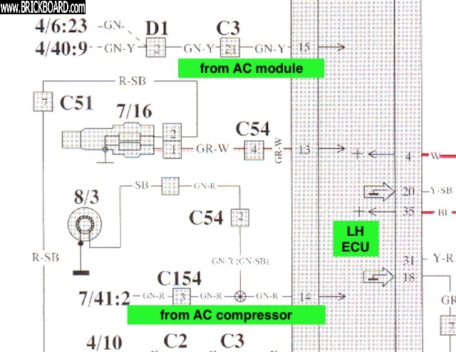
"But why are there TWO pins from the A/C to the ECU? ... I tried to trace them, could see where they (14: GN and 15: GR-R) entered the wiring loom, but didn't see them exit. Logically, there would be a connector left hanging somewhere from the loom."
Good questions. You and Art are looking at the A/C on the ECU, so I thought I'd look at it from the vehicle wiring perspective in case that triggers additional thoughts.
My theory is that pin 15 says the A/C compressor is about to kick in and pin 14 says it has kicked in, built on the following analyis:
First off, I note that when A/C is first engaged, idle is raised by 200 rpm only momentarily for a second or two in preparation to handle the initial inertia when the compressor kicks in. Once the compressor is running, maintaining idle under a minimal compressor load is no different than maintaining idle under any other load, such as an auto trans idling in gear. On the other side of the coin, switching off the compressor barely makes a 50 rpm hiccup in idle when the clutch releases so I rather suspect the ECU isn't doing a lot other than the usual matching IAC operation to CPS rpm to maintain the target idle speed.
Looking at the green manual wiring diagrams I have showing LH 2.4 with a B200F engine, they show a bit more detail for the ECU wiring than what you may be seeing on page 54 in that 240 Service Manual for LH 2.4 with a B230F. I couldn't find a green manual on-line for your 240, but the principles of operation I see in my 700/900 manuals of that vintage should be very similar for 240 LH 2.4 connections.
Pin 14 is from the A/C high pressure switch (a 12 volt source from the A/C delay relay connected to the dash switch) which also lets the ECU know when the compressor is actually engaged (or supposed to be engaged). That same signal goes from the high pressure switch to the compressor, hence why test E15 for pin 14 in the service manual says 0-5 Ohms between pin 14 and the A/C compressor to suggest they can both see the high pressure switch. If you don't have A/C, I quite expect pin 14 should simply be left open, not grounded. I expect the GN wire in your harness should go as a single wire to a main connector block in the engine compartment, where it should terminate and be available for dealer installation of A/C.
Pin 15 is directly from the A/C controller, which in the 240 is the console rheostat to indicate when A/C is being called for and perhaps even to what degree. It's not clear to me if this is being used as a variable resistance or more of an on/off type of signal. Why would it want to know how much A/C is being used, the compressor load is either on or off, not variable. What pin 15 might do though, is allow the ECU to get ahead of the delay relay and know the compressor will soon be kicking in, giving it a chance to raise the idle ahead of time. Now as much as test E15 says you should see approx 1K Ohms when A/C is off (10 Ohms when it's on), in practical terms for engine operation, the difference between 1K and infinite ohms seen by the ECU may make little or no difference. I expect the GR-R wire in your harness will go to a main connector block under the dash and terminate, waiting to have the dealer install an A/C switch. I'm very much guessing that without A/C, pin 15 can be left open, but certainly not grounded. In a non-A/C car, I somehow doubt you'll find a 1K resistor in a wiring harness or even in the ECU, that's too fussy for a dealer installable option. If pin 15 does actually care about variable resistance, then I imagine it does so for the purpose of altering fuel trim, not idle.
Not too sure how much of that helps you or how much of that I got slightly muddled, but you asked why two A/C connections on the ECU so I tried to do a bit of digging.
--
Dave -still with 940's, prev 740/240/140/120 You'd think I'd have learned by now
|
|
|
|
|
Thank you for that elaborate answer. I read quickly through it, I will read it a little more carefully later today.
In the mean time your description had me wonder about the function of pin 15.
If I look at the "Idling" column in the pinout diagram, two things stand out:
- pin 14 is Ulow when the A/C is off and Ubat when it's on
- pin 15 is Ulow when the A/C is off but Ubat when it's OFF/ON
That last thing seems to suggest that it's the transition from off to on that's accompanied by Ubat on that pin. Also, in the description the word "prepare" is used.
Those things have me puzzled a bit.
|
|
|
|
|
The LH2.4.4 ECU is digital based not analog. Its either ON or OFF. Its either Ubatt or Ulow.
Regarding pins 14 and 15 you should refer to latter wiring diagrams such as for 1994. In that diagram there are arrows which either go in or go out of the ECU. Pins 14 and 15 are labelled with "arrow in" which means the ECU only receives voltage input from compressor (pin14) and AC module (pin15). No voltage input means OFF. Since you don't have any resistors in the ECU for AC that leaves it out for causing idle increase.
Amarin
|
|
|
|
|
Yes, I now note that wording in the Jetronic Info wiki (I actually hadn't read that before my post, I was strictly looking at green manuals):
Pin 14 ... "Used to keep idling speed constant when air conditioning (A/C) compressor starts."
Pin 15 ... "Used to prepare the CIS valve before air conditioning (A/C) compressor starts."
It's all about preparing for and noticing the start of A/C operation, not during A/C operation, and that makes total sense to me while also agreeing with my own analysis. If the A/C sensing circuitry is involved with your idle problems, I think it would have to be some kind of semi-predictable interference or intermittence coming in on pin 15 to give your kind of symptoms. But your symptoms seem so much more associated with being in/out of gear, so I highly doubt that the A/C circuitry in the ECU is involved despite the magical 200 rpm number and why I pretty much discounted A/C operation being the source for you right from the start (just because you don't have A/C didn't mean the native A/C circuitry already there couldn't be an issue).
Your EZK and the wiring and circuitry associated with pins 8 and 16 smells much more interesting to me at this moment.
--
Dave -still with 940's, prev 740/240/140/120 You'd think I'd have learned by now
|
|
|
|
|
Art
Thanks for linking the old thread, I like the way you tested the in tank pump! I need to try it on my daughters 93 240.
Dan
|
|
|
|
|


